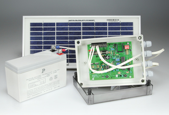
50-W Solar Cell Voltage Regulator
For 12-V lead-acid batteries and 12-15 V solar panels

Materials
Gerber file
CAM/CAD data for the PCB referred to in this article is available as a Gerber file. Elektor GREEN and GOLD members can exclusively download these files for free as part of their membership. Gerber files allow a PCB to be produced on an appropriate device available locally, or through an online PCB manufacturing service.
Elektor recommends the Elektor PCB Service service from its business partner Eurocircuits or AISLER as the best services for its own prototypes and volume production.
The use of our Gerber files is provided under a modified Creative Commons license. Creative Commons offers authors, scientists, educators and other creatives the freedom to handle their copyright in a more free way without losing their ownership.
Extra info / Update
Use of a switching step-down regulator reduces the power dissipated and improves efficiency.
The ATmega8 microcontroller turns off the electronics in the event of deep battery discharge; it starts it up again automatically as soon as the terminal voltage rises again above a certain threshold.
High and low thresholds can be set manually.
The regulator also takes into account the type of battery (lead-acid or gel) and the number of charge/discharge cycles so as to avoid the memory effect.
A serial link with a PC is possible by using a standard Elektor BOB-FT232R USB interface.
A remote control input makes it possible to turn on or off the user load circuit, for example using a time switch.
The software in Bascom–AVR can be modified to suit special requirements.
Components
The BOM (Bill of Materials) is the technically exhaustive listing of parts and other hardware items used to produce the working and tested prototype of any Elektor Labs project. The BOM file contains deeper information than the Component List published for the same project in Elektor Magazine. If required the BOM gets updated directly by our lab engineers. As a reader, you can download the list here.
Want to learn more about our BOM list? Read the BOM list article for extra information.
Component list
Resistors
Default: 0.25W 5%
R1,R6,R11 = 1kOhm
R4,R10,R17,R18,R19,R26 = 10kOhm
R3,R5,R9,R12,R15,R22-R25,R27 = 100kOhm
R20,R21 = 220Ohm
R13 = 51kOhm 1%
R14 = 12kOhm 1%
R8 = 18kOhm 1 %
R2 = varistor V33ZA5P
R7 = 100kOhm NTC
P1,P2 = 100 kOhm trimpot
Inductors
L1 = 10µH
L2 = 100µH
Capacitors
C1 = 470µF 35V
C2 = 22pF
C3-C5,C14,C18,C20 = 10nF 50V
C8,C11-C13,C15-C17,C19 = 100nF 50V
C9,C10 = 22pF
Semiconductors
D1 = 12V zener diode
D2,D3 = STPS745D
D4,D7,D13 = 5.1V zener diode
D5 = 1N5821
D6,D8,D9,D10,D14 = 1N4148
D11,D12 = 1N5819
LED1 = LED, green, high efficiency, 5mm
LED2 = LED, bicolor, 5mm, red/green
T1,T3 = STP22NF03L
T2,T4,T5 = BC547A
T6 = 2N7000
IC1 = LM2674N
IC2 = DS1813T
IC3 = ATMEGA8-16PU, programmed, Elektor Store # 080305-41
Miscellaneous
X1 = 4MHz quartz crystal
S2 = 4-way DIP switch
S1,S3 = pushbutton
F1,F2 = fuse, 3.15A, slow
K1 = 8-pin pinheader, 0.1’’ pitch
K2 = 3-pin pinheader, 0.1’’ pitch
K3 = 10-pin (2x5) pinheader, 0.1’’ pitch
J1,J2 = 2-pin pinheader, 0.1’’ pitch, with jumper
2 pcs. fuseholder, 5x20mm, PCB mount, with cap
2 pcs, heat-sink, TO220
Enclosure, 180x130x50 mm e.g. Fibox PC 150/50 LT
2 pcs. cable gland, straight, PG9
2 pcs. nylon nut
MOD1 = BOB-FT232R Elektor (optional)
PCB # 080305-1 [1]
R16,C7,IC4,P3 = not used.


Discussion (0 comments)