

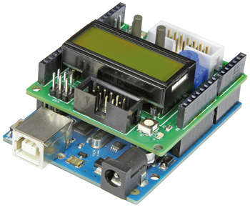
My First Shield :-)
LEDs, buttons and more
Gerber file
CAM/CAD data for the PCB referred to in this article is available as a Gerber file. Elektor GREEN and GOLD members can exclusively download these files for free as part of their membership. Gerber files allow a PCB to be produced on an appropriate device available locally, or through an online PCB manufacturing service.
Elektor recommends the Elektor PCB Service service from its business partner Eurocircuits or AISLER as the best services for its own prototypes and volume production.
The use of our Gerber files is provided under a modified Creative Commons license. Creative Commons offers authors, scientists, educators and other creatives the freedom to handle their copyright in a more free way without losing their ownership.
Components
The BOM (Bill of Materials) is the technically exhaustive listing of parts and other hardware items used to produce the working and tested prototype of any Elektor Labs project. The BOM file contains deeper information than the Component List published for the same project in Elektor Magazine. If required the BOM gets updated directly by our lab engineers. As a reader, you can download the list here.
Want to learn more about our BOM list? Read the BOM list article for extra information.
Component list
Resistors
R1,R2,R3,R4,R5,R6,R7 = 1kOhm
R8,R9 = 330Ohm
P1 = 10kOhm trimpot with adjuster
P2 = 10kOhm trimpot, SMD, Vishay TS53YJ103MR10
Semiconductors
LED1,LED2 = LED, low-current, red (SMD 0805)
LED3 = LED, low-current, green (SMD 0805)
Miscellaneous
S1,S2 = pushbutton
K1 = 10-pin boxheader, 0.1” pitch
K2 = 14-pin boxheader, 0.1” pitch
K3,K4,K5,K6 = Arduino Shield stacking header, Adafruit ID 85
K7 = 6-pin (2x3) pinheader, 0.1” pitch
JP1,JP2 = 2-pin pinheader with jumper, 0.1” pitch
LCD1 = LCD 2x8 characters with background lighting, Electronic Assembly DIPS082-HNLED
2 pcs. 7-way precision socket strip for LCD1, TE Connectivity 1814655-7
PCB # 140009-1 [1]
or
Assembled board # 140009-91 [1]
We buy at:

Discussion (0 comments)