Article
Elektor SDR Shield 2.0 (1)
Reception and tuning with this versatile new device

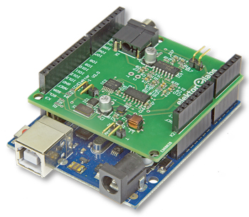
About two years have passed since the launch of the Elektor SDR Shield for creating a shortwave SDR using the Arduino [1]. Plentiful positive feedback and countless experiments have aroused the desire to provide greater connectivity onboard. SDR Shield 2.0 is now the basis for far more than simply a receiver. Applications range from a signal generator through shortwave transmitters all the way to forming a complete shortwave transceiver.First steps with G8JCFSDR
As not all readers will be familiar with the original SDR Shield, we ought to describe its beginnings here briefly.
Gerber file
CAM/CAD data for the PCB referred to in this article is available as a Gerber file. Elektor GREEN and GOLD members can exclusively download these files for free as part of their membership. Gerber files allow a PCB to be produced on an appropriate device available locally, or through an online PCB manufacturing service.
Elektor recommends the Elektor PCB Service service from its business partner Eurocircuits or AISLER as the best services for its own prototypes and volume production.
The use of our Gerber files is provided under a modified Creative Commons license. Creative Commons offers authors, scientists, educators and other creatives the freedom to handle their copyright in a more free way without losing their ownership.
PCB
Extra info / Update
Operating voltage: 5 V and 3.3 V from Arduino
Frequency range: 150 kHz to 30 MHz
Sensitivity: 1 µV
Overall gain: 40 dB
Maximum signal level at antenna: 10 mV
Dynamic range: 80 dB
Frequency range: 150 kHz to 30 MHz
Sensitivity: 1 µV
Overall gain: 40 dB
Maximum signal level at antenna: 10 mV
Dynamic range: 80 dB
Component list
Component List
Resistors
R1,R2,R13,R18 = 4.7kOhm, 1% 100mW, SMD 0603
R3,R4 = 330Ohm, 1% 100mW, SMD 0603
R5,R7,R8 = 100Ohm, 1% 100mW, SMD 0603
R6 = 470Ohm, 1% 100mW, SMD 0603
R9,R11,R14,R16 = 10kOhm, 1% 100mW, SMD 0603
R10,R12,R15,R17 = 100kOhm, 100mW, SMD 0603
Capacitors
C1,C18 = 4.7µF 16V, SMD case B
C2,C3,C6,C7,C8,C9,C12,C13,C14,C15,C16,C17,C19 = 100nF 50V, X7R, SMD 0603
C4,C5,C10,C11 = 2.2µF 50V, X7R, SMD 0603
Inductors
L1 = 2200µH (Fastron L-1812AF)
L2 = 10µH (Murata LQH32CN101K23L)
Semiconductors
D1,D2 = 1N4148WS, SOD-323
T1 = BF545B, SOT-23
IC1 = SI5351A-B-GT, MSOP-10
IC2 = SN74AC74PW, TSSOP-14
IC3 = 74HC4066, SOIC-14
IC4 = TI914IDT, SOIC-14
Miscellaneous
K1 = stereo jack, 3.5mm, PCB mount
K2,K3,K4,K5 = 1 set of Arduino-compatible interconnection socket strips, (1x 6-pin, 2x 8-pin, 1x 10-pin)
X1 = 25-MHz quartz crystal (Abracon ABM7)
PCB 170515-1
or
PCB with SMDs preassembled: 170515-91


Discussion (0 comments)