

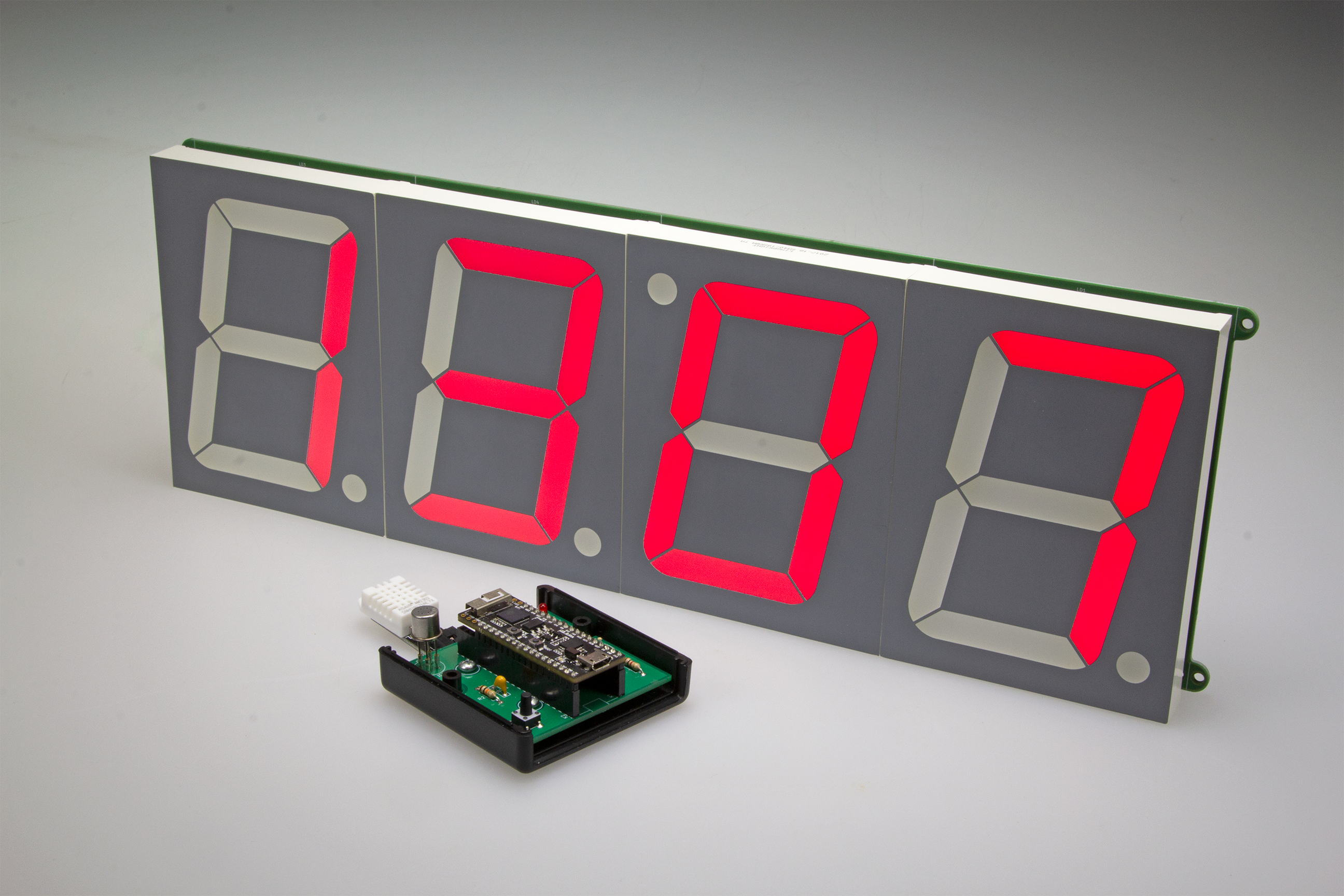
A Monster LED Clock with Wi-Fi and Temperature Display
4-inch tall display, Internet time via ESP32, and remote sensors
Gerber file
CAM/CAD data for the PCB referred to in this article is available as a Gerber file. Elektor GREEN and GOLD members can exclusively download these files for free as part of their membership. Gerber files allow a PCB to be produced on an appropriate device available locally, or through an online PCB manufacturing service.
Elektor recommends the Elektor PCB Service service from its business partner Eurocircuits or AISLER as the best services for its own prototypes and volume production.
The use of our Gerber files is provided under a modified Creative Commons license. Creative Commons offers authors, scientists, educators and other creatives the freedom to handle their copyright in a more free way without losing their ownership.
Components
The BOM (Bill of Materials) is the technically exhaustive listing of parts and other hardware items used to produce the working and tested prototype of any Elektor Labs project. The BOM file contains deeper information than the Component List published for the same project in Elektor Magazine. If required the BOM gets updated directly by our lab engineers. As a reader, you can download the list here.
Want to learn more about our BOM list? Read the BOM list article for extra information.
Component list
Component List, display board
Resistors
All SMD 0805, 0.25W
R1 = 1kΩ 10kΩ
R5-R11,R13-R19,R21-R27,R29-R35 = 43Ω *
R12,R20,R28,R36 = 680Ω *
Capacitors
C1 = 100µF, 25V, radial, 2.5mm lead pitch
C2 = 330nF, 50V, X7R 0805 *
C3,C6,C7 = 100nF, 50 V, X7R 0805*
C4,C5 = 1µF 50V, X7R 0805
Semiconductors
D1 = MBR540
LD1-LD4 = SA40-19SRWA, Kingbright, e.g. Reichelt SA40-19RT *
IC1 = 7805, 5-V voltage regulator*
IC2 = ULN2803A, SOIC18-W
IC3 = MIC2981, SOIC18-W
Miscellaneous
ESP32 Pico Kit, Espressif [1]
PCB-mount power barrel socket, straight or right-angled. (Würth 694108402002 or 694108301002) *
2x20-way pinheader sockets for ESP32, SIL, 0.1“ pitch
K1 = 2-pin pinheader, 0.1“ pitch
K2 = 6-pin pinheader, SIL, 0.1“ pitch
K3,K4,K5,K11 = 4-pin pinheader, SIL, 0.1“ pitch
PCB # 180254-1 v1.2 (Elektor Store)
* = see text
Component List, sensor board
Resistors
All through-hole, 0.25W
R1,R2 = 10kΩ
R2,R3,R4 = 1kΩ
R5,R6,R7 = 220Ω
Capacitors
C1 = 100nF, 50V, ceramic, radial, 5mm pitch
Semiconductors
LED1,LED2,LED3 = red, 3mm diam.
D1 = BAT85
T1 = BS170
IC1 = TGS2600, Figaro
Miscellaneous
ESP32 Pico Kit, Espressif [1]
Sensor module DHT22, Air temperature and humidity *
Buz1 = piezo buzzer, e.g. PS1420P02CT, TDK
K1,K2 = 20-way pinheader socket strip for ESP32, SIL, 0.1“ pitch
K3= 3-pin pinheader, right-angled, 0.1“ pitch
S1 = pushbutton, SMD, e.g. S-TACTILE-6X6-PTH, Alps
PCB # 170182-1 v1.1 (Elektor Store)
* see text
We buy at:

Discussion (0 comments)
old-maker 5 years ago
I would like to report some errors in the project "Monster LED Clock" (Elektor 3/2019), related to the component lists in the article and above all to the BOM files on the site.
Display board:
- R1 value in the article is "1k 10k" (?) and in the BOM file is 1k, but I think it should be 10k; therefore also the Farnell and RS references in the BOM are wrong;
- R12, R20, R28, R36 value is 680R, but in the BOM file it becomes 680k; therefore also the Farnell and RS references in the BOM are wrong;
- C2: the Farnell and RS references in the BOM are wrong;
- D1: in the component list there is MBR540, hard to find in package SMB or SMC (SMD 2 pin); in the BOM file there is MBRS540, easy to find; is it the same ?
- LD1, LD2, LD3, LD4: the BOM quantity is 1 instead of 4;
- MOD1 socket: the BOM reports "Pin socket, breakable, 2 rows, 72-way, vertical", but it should be "Pin socket, 1 rows, 20-way, 2,54 mm, vertical, THT", quantity 2; therefore also the Farnell reference in the BOM is wrong;
- PCB # 180254-1 v1.2 not reported in BOM file.
Sensor board:
- R2: in the component list is reported twice, one as 10k and one as 1k; I think it should be 10k, as in BOM;
- IC1: the TGS2600 is avalable at RS, with reference 134-6669;
- S1: in the component list is reported as SMD, but in my opinion it's THT;
- Sensor module DHT22: not present in BOM file; avalable at Farnell, with reference 2801405.
I'd have two further question (in addition to D1):
- In the photos, the sensor board is perfectly fitted in a case; which model of case is it ?
- The display board is very large and can contain a lot of component; why to use SMD components? Do you like to suffer ? :-) :-)
Thank you. Bye.
Pasquale D'Antini
ElektorLabs 5 years ago
for the Monster LED Clock the BOM is corrected. Thanks for the information provided. About the MBRS540, yes you can use that one. For the R1 being 1k, as the ESP32 may have some issues with the Bootstrap, the 1k simply help to prevent ending in bootloader.
The housing for the enviromental sensor is a : HAMMOND 1593KBK
Using SMD on the clock was easyer than using THT in terms of soldering, as you don't have to flip the board to get the components in place. But this is a very personal opinion of SMD vs. THT .
The BOM for 170182 will be updated soon.
Best Regards
ElektorLabs