

The Elektor LoRa Node
Versatile, long-range, 868-MHz remote control with state feedback and STM32 Inside
Gerber file
CAM/CAD data for the PCB referred to in this article is available as a Gerber file. Elektor GREEN and GOLD members can exclusively download these files for free as part of their membership. Gerber files allow a PCB to be produced on an appropriate device available locally, or through an online PCB manufacturing service.
Elektor recommends the Elektor PCB Service service from its business partner Eurocircuits or AISLER as the best services for its own prototypes and volume production.
The use of our Gerber files is provided under a modified Creative Commons license. Creative Commons offers authors, scientists, educators and other creatives the freedom to handle their copyright in a more free way without losing their ownership.
Components
The BOM (Bill of Materials) is the technically exhaustive listing of parts and other hardware items used to produce the working and tested prototype of any Elektor Labs project. The BOM file contains deeper information than the Component List published for the same project in Elektor Magazine. If required the BOM gets updated directly by our lab engineers. As a reader, you can download the list here.
Want to learn more about our BOM list? Read the BOM list article for extra information.
Component list
Component List
For LoRAWAN Experimental Platform board
Note: 2 required, 1 for Switch, 1 for Button.
Resistors
R1 = 100kΩ, thick film, 5%, 0.1W, 150V
R2,R10 = 680Ω, thick film, 5%, 0.1W, 150V
R3,R8,R9 = 4.7kΩ, thick film, 5%, 0.1W, 150V
R4,R5,R11 = 10kΩ, thick film, 5%, 0.1W, 150V
R6,R7 = 150kΩ, thick film, 5%, 0.1W, 150V
Capacitors
C1,C5,C8,C14,C15 = 4.7µF, 16V, X7R, SMD 0805
C2,C3,C7,C9,C10,C11,C12,C17,C18 = 100nF, 50V, X7R, SMD 0805
C4 = see text
C6 = 470nF, 25V, X7R, SMD 0805
C16 = not fitted
C20 = not fitted
C19,C21 = 100µF, 10V, SMD 1206 [3216 Metric], ± 20%, X5R
Semiconductors
D1 = PMEG3010EJ, 115, diode, 30V, 1A
LED1 = low current, red, SMD 0805
LED2 = low current, green, SMD 0805
T1 = SI2347DS, MOSFET, p-channel, 5A, 30V, 0.033Ω
IC1 = TLV809K33DBVR, voltage supervisor
IC2 = TLV75533PDBVR, 3V3 LDO, 500mA, low-IQ, SOT-23-5
IC3 = optional. Space for: AT25SF081-SSHD-T 8Mbit flash IC
IC4 = STM32F072C8T6TR ARM Cortex-M0 microcontroller
IC5 = optional. Space for: ATECC608A-SSHDA-B, CryptoAuthentification
IC6,IC7 = MAX40200AUK+T ‘Ideal Diode’ controller, 1-channel, 1A
MOD1 = RFM95W-868S2 LoRa transceiver, Elektor Store SKU 18715
Miscellaneous
X1 = 32.768 kHz oscillator module, SMD, 3.2mm x 1.5mm (Abracon ASH7KW-32.768KHZ-L-T)
S1,S2 = switch, tactile feedback, 12V, 50mA (Multicomp TM-553I-Q-T/R)
Bt1, Bt2 = optional. Space for: AAA battery holder with PCB pins (Multicomp MP000341)
F1,F2 = 500mA PPTC resettable fuse (Bel Fuse 0ZCK0050FF2E)
K1 = PCB pin
K2 = 2-pin pinheader
K3 = 4-pin SIL pinheader
K4 = 5-pin pinheader
K5 = 17-way SIL pinheader
K6 = 3-pin pinheader
K5,K6,K3,K4 = 40-pin SIL pinheader
ANT1 = Wire antenna, 1mm enamelled copper wire, length 8.2cm
PCB 180516 V3.1 from Elektor Store
Component List
For Lora AC Switch Board
Resistors
R1 = NTC, 120Ω, Epcos type B57236S0121M000
R2,R3 = 10Ω, carbon film, 5%, 0.25W, 250V
R4 = 100kΩ, carbon film, 5%, 0.25W, 250V
R5,R6 = 47kΩ, carbon film, 5%, 0.25W, 250V
R7,R8 = 1kΩ, carbon film, 5%, 0.25W, 250V
Inductor
L1 = ACM4520V-231-2P-T common-mode filter (Farnell # 2455201)
Capacitors
C1,C2 = 100nF, 50V, X7R, 0.2’’ (5.08mm) pitch
C3 = 1µF, 16V, radial, 5mm
C4 = 10µF, 16V, radial, 5mm
Semiconductors
D1,D2 = 1N4148
D3 = 1N4007
T1,T2 = BS170
IC1 = CNY65 optocoupler
Miscellaneous
RE1 = G5RLK1AEDC5 power relay, latching dual coil, 5V, 16A, SPST (Omron)
K1,K2 = 3-way PCB screw terminal block, 0.3’’ (7.62 mm), 500V
K3 = 2-row board-to-board connector, 0.1’’ (2.54mm) pitch, 16 contacts, receptacle, WR-PHD series, surface mount (Würth # 610316243021)
S1 = Pushbutton switch, IP68 class (Alcoswitch PB6B2FM3M1CAL07)
MOD1 = AC/DC PCB mount power supply 5V, 200mA (Mean Well IRM-02-5)
F1,F2 = Fuseholder, PCB mount, 5x20mm
F1 = 60mAT fuse, 20mm
F2 = 5AT fuse, 20mm
PCB 180666-1 V1.1 from Elektor Store
Case: HAMMOND 1591-ATBU (Ice Blue)
Component List
For LoRa Button board
Resistors
R1 = 270Ω, carbon film, 5%, 0.25W, 250V
R2 = 10kΩ, carbon film, 5%, 0.25W, 250V
R3,R4 = 680Ω, carbon film, 5%, 0.25W, 250V
Semiconductors
LED2 = red, 3mm
LED1 = green, 3mm
Miscellaneous
K2,K4 = 2-way PCB screw terminal block, 0.2’’ pitch (5.08mm), 630V
K3 = pinheader socket, breakable, 1 row, 5-way, vertical
K5 = pinheader socket, breakable, 1 row, 17-way, vertical (see text)
K6 = Pinheader socket, breakable, 1 row, 3-way, vertical
1 pc. Switch with blue integral LED
Miscellaneous
Blue 0.96" OLED display, I²C, 4-pin (optional)
PCB 180666-2 V1.2 from Elektor Store
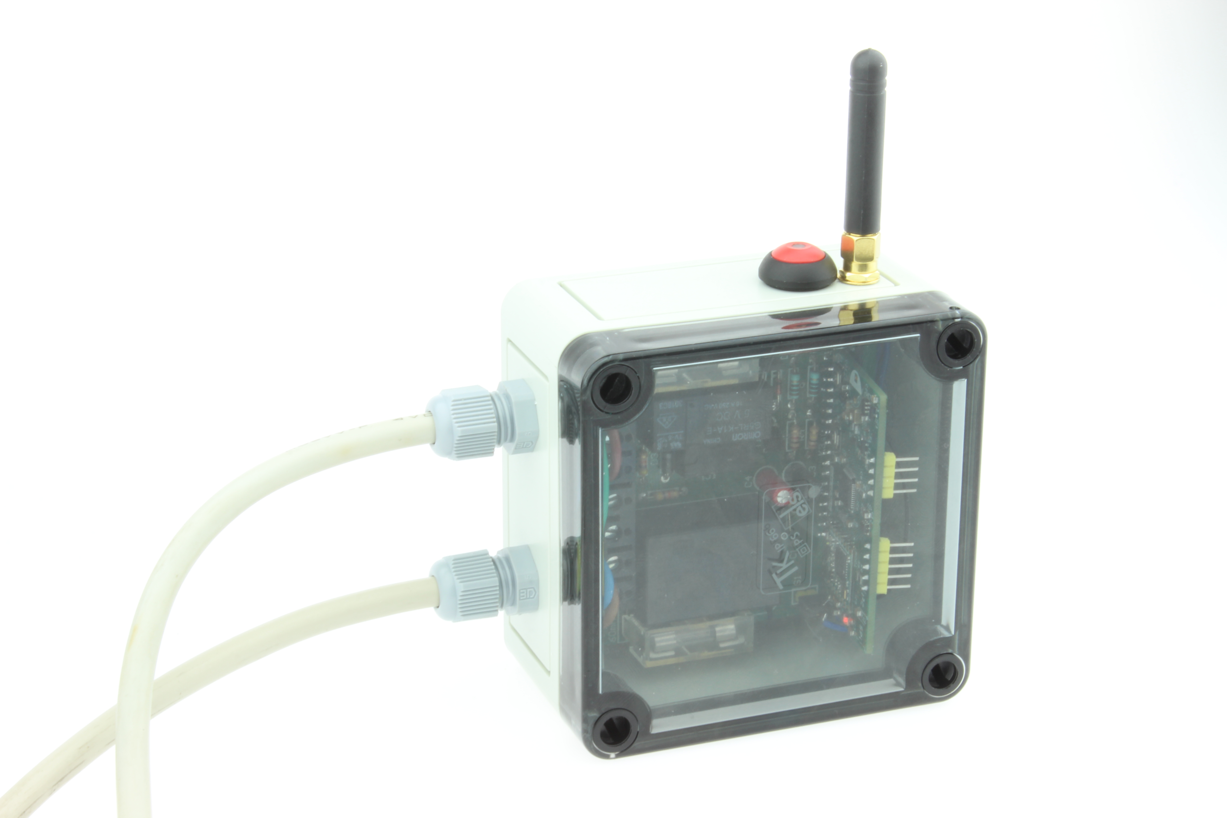
Case: Spelsberg type TK PS 94 x 94 x 57 mm, IP66
We buy at:

Discussion (0 comments)
JohnDoe 4 years ago
Congratulations for this project which is a very good introduction to LPR. Looking into the code, I see that there is a sort of "synchronization" between the transmitter and the receiver (with the framecounter variable), which does'nt allow to have multiple transmitters with only one receiver. So, to controll a receiver from several transmitters, this "protocol" has to be modified, am I wrong?
Best regards,
Denis
JohnDoe 4 years ago
Nevertheless I started to examine the software and found some problems:
- first, you must configure the MCCI library for the European region (it is US by default)
- The receiver software compiles without any problem, with last version of MCCI (3.1.0)
- But the transmitter does not compile with that version, the code is too big
- So, I get back to 2.3.2 and get compilation errors
- Finally, revert back again to 2.3.1 and then compilation is OK, but the code takes 98% of the memory, wich is not a good situation for future enhancements (disabling PING and BEACONS in the conf file do nothing on the size).
I intend to use the "B" version of the STM32F072C, with 128kB of memory. Again, some configurations files to modify (boards.txt, ldscript.ld).
I also will modify the receiver board to have a dry contact, instead of switching main, and use a DPDT dual coil relay to have a simplest way with the second contact to know the state o fthe relay.
And finaly implement a multi-transmitter version, where the emitter will have an ID and the receiver will manage a frame counter per emitter ID. The final purpose is a remote control for the gate of our private compound: 17 houses, some being more than 300m from the gate.
ElektorLabs 4 years ago
Thank you for the comments on the Elektor LoRa Node. Referring to your posts, the software was designed with primarily one receiver and one transmitter in mind. More than one transmitter does work, but this will cause a lot of resync operations so the default state is indeed not ideal. For a given set of transmitters the required modification to the code is modest, so if you could indicate an expected number of remotes you planned to use?
We confirm that the information as provided lacks details on changing the country settings for the appropriate region, we will add the information to the article and to the project files proper..
Regarding the code size, during development we used the MCCI 2.3.1 and yes it was a tight fit inside the stated MCU, so we will change the BOM and recommend to use the larger STM32F072CB type to leave some room for more user code. Consequently we will file the ‘B’ type as a request to STM32duino, so this should be an out of the box option at some point in the IDE.
We are happy to get feedback for the project so we can improve it further and eliminate any glitches that may have come up during development. That’s why we ask you to share the findings also on our labs website ( https://www.elektormagazine.com/labs/lora-controlled-switch-with-state-feedback ) as well as details on the application you are working on. With your cooperation and for the benefit of other readers we’d then report on what you intend to build based on the Elektor Lora Based Switch. In that case please drop a short mail or message to the editors of Elektor.
Best Regards
Elektor Labs
HaSch 3 years ago
I set up a slave unit and did some tests with it. First of all it isn't possible anymore to compile under new board package 2.1.0 (error message: LoRa_Switch_Receiver:1009:44: error: no matching function for call to 'HardwareTimer::attachInterrupt(void (&)(HardwareTimer*))' 1009 | MyTim->attachInterrupt(Update_IT_callback);). Even using board package 1.9.0 the same error appears, under 1.8.0 all goes well.
Hope somebody can help me with another issue:
If the switch is unplugged and reconnected, it will have forgotten the last relay state. The board always switches off the relay in the event of a power failure. This is bad because it's built in a bistable relay that retains its last state. So it would be good if that could be the case in practice. I tried to query the state in the sketch via the optocoupler and to set the relay accordingly when powering on, but that doesn't work. Everything seems to set to zero again apparently when restarting. One possibility would be to save the relay state in the EEPROM. For that one would have to know how the memory allocation is organized. Is there any information about this?
Kind regards,
Hans
HaSch 3 years ago
Aside from that I recognized that master unit of the switch needs compilation under 1.7.0 of boards package. This package needs to be modified as described in Elektor article. If compiled under 1.8.0 or newer it throw an error. In this respect the last paragraph of the article is not correct.
schofiel 2 years ago
Alternatively, can you commit your source changes to the GitHub repository?
Rob
HaSch 2 years ago
here are my files without any garantee. I think it are the right (corrected) ones but I'm not sure. It's been a long tome since I worked on this project. Please feel free to test.
Using LoRa transmitter is a bit disappointing because lifetime of batteries is really short. If you would seriously use this project I recommend to use it with WLAN module instead of LoRa as described by Clemens Valens here.
Best regards,
Hans
LoRa_Switch_Transmitter.zip (18kb)
Mathias_Claussen(Elektor) 2 years ago
thanks for sharing your updated files.
Best Regards
Mathias Claußen