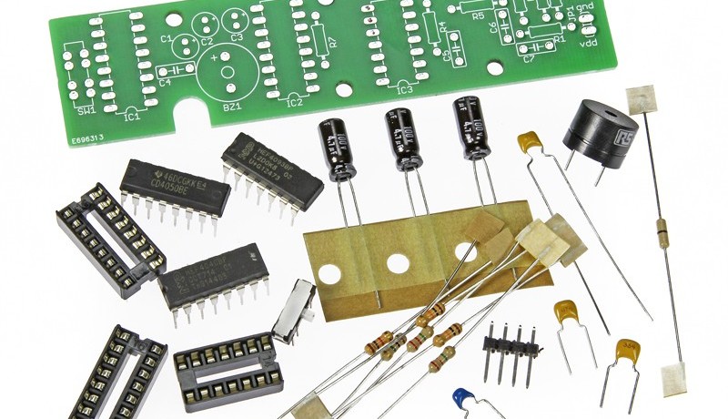
Beep: Logic Probe/Tester
January 01, 2015
on
on

Even if you have an upmarket logic analyzer and are completely at ease with its operation, you are unlikely to use it to debug simple circuits like Arduino and Raspberry Pi add-on boards. That’s where Beep comes in.
For sure a common digital multimeter can be used too, but it’s a pain to watch its display all the time to see your measurement results. It’s even harder when you have to keep a probe tip lodged on a small pin. Do the zero volts on that DMM display mean that the level of the signal under test (SUT) is low, or is it because the test probe slipped off the pin and has gone unconnected? Woes like these triggered us to develop the logic probe presented in this article.
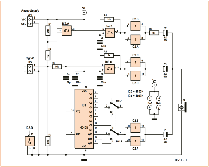
Figure 1: Beep’s schematic. R7 is zero ohms and represents a wire bridge.

Read full article
Hide full article


Discussion (0 comments)