Bright Flashing LED – traditional analogue...
on
 A flashing LED? What is so special about that, you may well ask yourself. A microcontroller plus a handful of discrete parts, and Bob's your uncle – isn't it? Still, many readers love analogue electronics and so we present a variant that is built entirely from discrete parts and hopefully triggers your own experimentation!
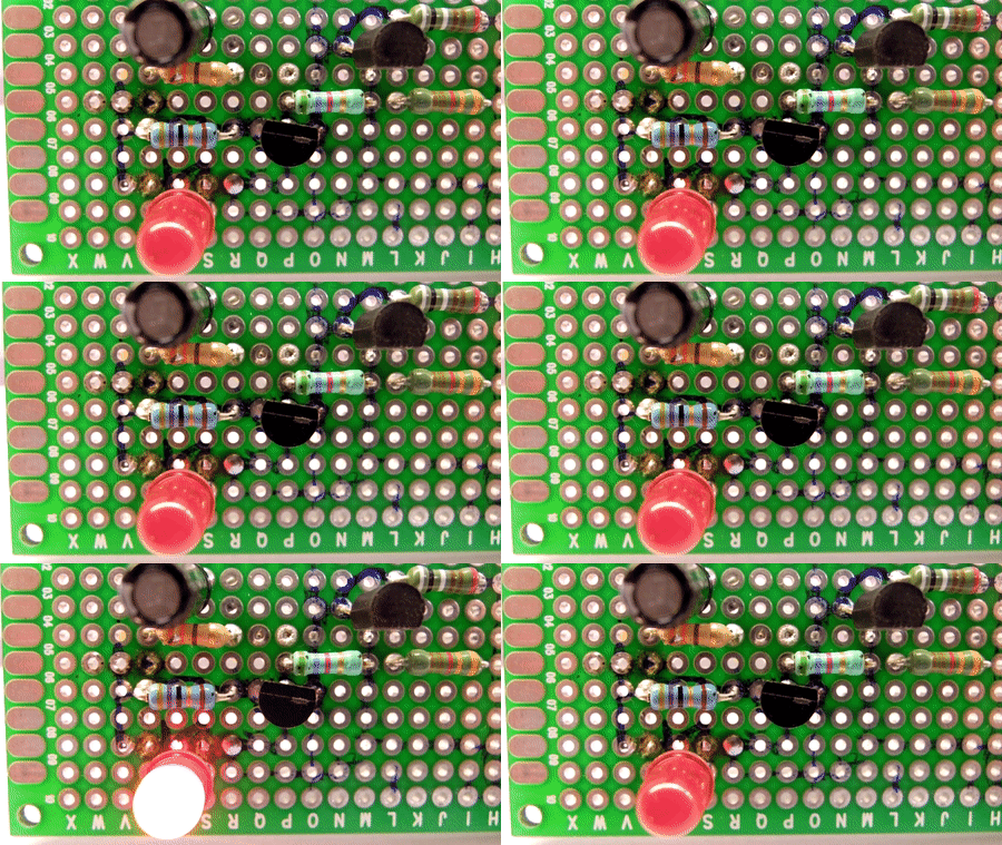
The author has kept himself busy professionally with the design of (mainly) analogue chips. But to prove that you don't always have to use an IC, and also because it is sometimes just fun to figure out an analogue circuit, he presents here a flashing LED that needs no more than a couple of transistors and a handful of small parts. The result is shown below.

The operation of the circuit is best described as follows. For convenience we start with the situation where the voltage at node 1 is relatively low. A current flows towards node 3 via R3 and R4 (and therefore also R2), but the current is not large enough to turn T1 on.
Capacitor C1 is continually being charged through resistor R1; once R1 (via T2) also starts to supply current towards node 3, the sum of the currents becomes large enough for T1 to turn on. The voltage at node 2 will be pulled low and the circuit locks itself in this state (functions as a latch).
The current towards node 3, via resistor R3, now stops, but instead capacitor C1 is discharged (via T2) and the LED lights up brightly. As C1 discharges, the current through T2 towards node 3 diminishes until it is no more than what is supplied via R1, and that is not enough to keep T1 turned on. Node 2 will now be pulled high by R4, which turns T2 off. At this instant the entire cycle begins again.
Resistor R5 has an important function as a bypass: without this resistor, the LED would cause a threshold voltage that is too high for T1 to turn on, with the consequence that the latching action doesn't happen. The bypass current amounts to about 10% of the LED current.
Note that the LED flashes very brightly (with the component values indicated, at a rate of about 0.8 Hz); a simulation (in LTspice XVII) indicated a value of about 600 mA. Of course it is not ideal when the capacitor is discharged only through the transistors and the LED; you can experiment here with a current-limiting resistor (which, by the way, will also increase the duration of the flash).
Audio variant
If you have an appetite for that, you can also build an audio variant of this circuit. The circuit remains practically the same; only the component values need to be changed as follows:Resistors: R1 = 3k9; R2 = 180 Ω; R3 = 2k7; R4 = 1k8; R5 = 15 Ω.
Capacitor: C1 = 0.2 µF.
Transistors: T1 = BC109C; T2 = BC240B (not critical, any TUP and TUN will do).
The loudspeaker (8 Ω) is connected between C1 and ground; the LED is omitted.
This variant generates a (somewhat objectionable) sound with a frequency of about 1 kHz. However that would be perfectly suitable for alarm applications.
The construction of the circuit is not very critical; a small piece of prototyping board is more than sufficient.
(180542)
➔ Do you want to read more ElektorLabs articles? Become an Elektor member now!


Discussion (3 comments)