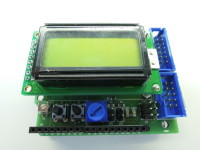
Remake Arduino course shield [160593]

New version of 140009, new LCD with Backlight!
The 'old' board is still very popular among our readers, so it's time to give it a facelift :-) We decided to use a different type of LCD mainly because the pinning of the EA DIPS082 display used in the original design is rather exotic. On this new board, you can hook up any alfanumeric LCD module with a standard 2x8 pin connector, so it's not limited to connecting a 2-lines and 8-characters display.
We had to redesign the PCB and the component placement differs from the 140009 board, but the electronics and functionality of the boards are completely identical, except for the brand/type of the display of course.
The ready-made boards in our shop will be sold with a 2x8 LCD with backlight.
See also:
https://www.elektormagazine.com/labs/arduino-experimenting-evaluation-and-expansion-shield-arduino-eee-140009-i
BOM 160593-1:
Resistor
R1,R2,R3,R4,R5 = 1K 5% 125mW
R6,R7 = 100R 5% 125mW
R8,R9 = 330R 5% 125mW
P1 = trimmer 10k with knob
P2 = trimmer 10k SMD Vishay TS53YJ103MR10
Semiconductor
LED1,LED2 = low current LED red 0805
LED3 = low current LED green 0805
Other
S1,S2 = tactile switch SPST
K1 = box header 2 x 5 pitch 100mil
K2 = box header 2 x 7 pitch 100mil
K3,K6 = 8-way pin header single row
K4 = 10-way pin header single row
K5 = 6-way pin header single row
K3,K4,K5,K6 = Shield stacking headers for Arduino, pin length 15mm
K7 = pin header 2 x 3 pitch 100mil
JP1,JP2 = 2-way pinheader pitch 100mil
jumper socket 100mil
LCD1 = LCD 2 x 8 characters with backlight, TC0802B
LCD1 = pin header 2 x 8 pitch 100mil
LCD1 = socket 2 x 8 pitch 100mil
2 pcs. 7-way receptable single row for mounting LCD1
Misc.
PCB 160593-1 V2.1
LCD1 = 4 pcs machine screws M2.5 x 20
LCD1 = 12 pcs nuts M2.5


Discussion (0 comments)