
Short Circuit Probe
SCC-2024 is a porting from an initial EB (Electro Bidouilleur) solution called Sonde de court-circuit "délicate". This new realization add visualisation and another features. Also the code was ported from C language to GCBASIC.
Hello Community,
Let me introduce you my latest vacation project! It's a code porting and PCB creation of an electronic project originally designed and presented by Bertrand, aka EB (Electro-Bidouilleur).
In 3 YouTube videos (the links are in the source code or here), Bertrand created and described a “delicate” short-circuit probe based on an operational amplifier and a Microchip PIC12F683 microcontroller. The probes approach the cause of the short-circuit acoustically (rather than visually). Detection of the short-circuited component or track is very precise using Bertrand's approach.
The whole project folder is shared on google drive. You can find it here:
https://drive.google.com/drive/folders/1I37gtDkziqW8wk-YkMkuPJLwEpv4VHwi?usp=drive_link
So it was this that I had to reproduce and develop a suitable printed circuit board for surface-mounted components. I also use an identical Teko package for several of my assemblies. Here too, I was going to make a front panel in 1.5mm thick GFK black epoxy, engraved and cut by a CNC milling machine.
For many years, I had been using Eagle software to design my printed circuit boards. It was time for me to learn a new tool, in this case KiCad, to design my future assemblies. I'd started learning KiCad by converting one of my documentary projects, PWM2Laser. One of the reasons I didn't want to leave Eagle was the CAM tool developed by John T.Johnson, PCB-Gcode, an ULP addon to Eagle which I used to produce the gcode files needed to isolate per CNC the circuit boards.
In fact, when I was developing circuits, I often first produced a PCB prototype with the CNC milling machine, using isolation passes. As I hadn't yet found a new CAM (and post- processor for Mach3) for KiCad, I was naturally dragging my feet about converting to KiCad. In the meantime, I discovered the LineGrinder software developed by Nic. I'm still getting the hang of it, but it will certainly enable me to switch from Eagle to KiCad for milled circuit boards.
Using KiCad a little more now as for my PCB single-sided board (although LineGrinder does contain a function for making double-sided boards), I now had to make the step up to a double-sided board with plated-through holes, to be produced by a PCB factory. The idea was born to give Bertrand's project a PCB, and at the same time to port EB's initial C language code to a language I know better, BASIC!
Getting back to the tools I use for my microcontroller-based creations, I had been using MikroElektronica's MikroBasic environment for several years. Since then, I've discovered GCBASIC (with a top-notch support team), an open source environment dedicated to PIC and AVR (8-bit) microcontrollers.
Let's combine the 2, KiCad and GCBASIC. I took the opportunity to replace the original microcontroller used by EB, a PIC12F683, with a PIC16F1825. Why a PIC16F1825? Because I still have quite a few in my drawers and it's in production at Microchip, so it's not difficult or expensive to obtain. It also contains enough programming memory to support the functionality of the short-circuit detection probe.
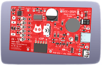
So, in addition to the probe's audible indications, I've also added a visual indication in the form of a bar graph with 6 different-colored LEDs. You'll also find in my approach an electronic part to manage the electronic power supply, as well as a charging module for the electric battery. The board contains several test points, designed to be used as a prototype and development board. Several soldering bridges allow optional use of certain components, such as the battery charger or voltage regulator. For more information, take a look at the KiCad schematic provided in the project file. The project was named SCC-2024 for Sonde de Court-Circuit (vacations 2024)!
You will certainly recognize in the diagram modules and functions designed by other people in the community, perhaps even one of you currently reading this presentation. I've been able to note and name the people whose references I've been able to find, but unfortunately for some parts, such as the electrical interruption management and its push-button management, I haven't been able to find its origin. If you know its designer, please let me know.
So there you have it, the result of my vacation work is now available and shared with the whole community. If you have any ideas for improvements, particularly to the code - in fact, there's a routine (the LED display) that could well be revised in a way that's probably more elegant than the one I've come up with (I'm not the specialist in algorithms) - you can use my e-mail address to contact me or share here. I'd be delighted to talk to you.
Thanks to everyone for making this project possible, especially Bertrand EB for his initial idea and sharing, the GCBASIC team, especially Evan and Angel, the KiCad team, John and Nic, and I'm sure I'm forgetting too many. Thanks to all of you! Until next time…
Update from the 5 th of August 2024:
Now that I had a second SCC-2024 module assembled, I had to review the ADC data calibration values for the battery voltage control measurements. During these measurement operations, I became aware of a problem with excessive current consumption from time to time when the buzzer stopped sounding.
In fact, I've recently been using a new laboratory power supply with a much more comprehensive display than the one used at the start of the project. This highlighted abnormal current consumption in particular situations. When the buzzer made a random sound, the electronics consumed more current than normal. What could be causing this?
Let's take a look at how the buzzer is activated to emit sounds. The buzzer is alternately powered by the microcontroller's interrupt management, at particular frequencies, simply by changing the buzzer's control state from 0 to 1, from Off to On, each time the routine is run. This electrical level switch generates the buzzer sound signal.
By exiting the interrupt routine in the PIC program, the buzzer control can be set to 0 or 1, Off or On. And if, from that moment on, the buzzer was no longer to emit any sound, but its control state remained at 1, I'll leave you to imagine the rest. What may seem obvious, but was not in my mind at the time of re-coding Bertrand's program, is that I should have paid attention to the output state of the buzzer command at the end of sound frequency generation.
This has now been done, and version V1.2 of the software contains these associated commands. I don't have much experience of the long-term use of buzzers, but what can happen if a current (which is quite high, given its specifications) flows permanently through the buzzer? To avoid any problems, I recommend replacing the previous code (if you've already programmed it in your PIC) with this new V1.2 version.
Version V1.2 also contains new values for the battery voltage detection thresholds, and a slightly adapted parameter for a better sound experience (constant BuzzerReloadDelaySet). The battery voltage display routine has also been corrected. The value displayed was compared to the last average value stored in EEPROM, and could be erroneous if the difference was too great. You can find out more in the source code comments.
Update from October 2024:
I wrote a short notice how to use the Short Circuit Probe SCC-2024. It is now available in the download section 'Other'.
Let me introduce you my latest vacation project! It's a code porting and PCB creation of an electronic project originally designed and presented by Bertrand, aka EB (Electro-Bidouilleur).
In 3 YouTube videos (the links are in the source code or here), Bertrand created and described a “delicate” short-circuit probe based on an operational amplifier and a Microchip PIC12F683 microcontroller. The probes approach the cause of the short-circuit acoustically (rather than visually). Detection of the short-circuited component or track is very precise using Bertrand's approach.
The whole project folder is shared on google drive. You can find it here:
https://drive.google.com/drive/folders/1I37gtDkziqW8wk-YkMkuPJLwEpv4VHwi?usp=drive_link
So it was this that I had to reproduce and develop a suitable printed circuit board for surface-mounted components. I also use an identical Teko package for several of my assemblies. Here too, I was going to make a front panel in 1.5mm thick GFK black epoxy, engraved and cut by a CNC milling machine.
For many years, I had been using Eagle software to design my printed circuit boards. It was time for me to learn a new tool, in this case KiCad, to design my future assemblies. I'd started learning KiCad by converting one of my documentary projects, PWM2Laser. One of the reasons I didn't want to leave Eagle was the CAM tool developed by John T.Johnson, PCB-Gcode, an ULP addon to Eagle which I used to produce the gcode files needed to isolate per CNC the circuit boards.
In fact, when I was developing circuits, I often first produced a PCB prototype with the CNC milling machine, using isolation passes. As I hadn't yet found a new CAM (and post- processor for Mach3) for KiCad, I was naturally dragging my feet about converting to KiCad. In the meantime, I discovered the LineGrinder software developed by Nic. I'm still getting the hang of it, but it will certainly enable me to switch from Eagle to KiCad for milled circuit boards.
Using KiCad a little more now as for my PCB single-sided board (although LineGrinder does contain a function for making double-sided boards), I now had to make the step up to a double-sided board with plated-through holes, to be produced by a PCB factory. The idea was born to give Bertrand's project a PCB, and at the same time to port EB's initial C language code to a language I know better, BASIC!
Getting back to the tools I use for my microcontroller-based creations, I had been using MikroElektronica's MikroBasic environment for several years. Since then, I've discovered GCBASIC (with a top-notch support team), an open source environment dedicated to PIC and AVR (8-bit) microcontrollers.
Let's combine the 2, KiCad and GCBASIC. I took the opportunity to replace the original microcontroller used by EB, a PIC12F683, with a PIC16F1825. Why a PIC16F1825? Because I still have quite a few in my drawers and it's in production at Microchip, so it's not difficult or expensive to obtain. It also contains enough programming memory to support the functionality of the short-circuit detection probe.
So, in addition to the probe's audible indications, I've also added a visual indication in the form of a bar graph with 6 different-colored LEDs. You'll also find in my approach an electronic part to manage the electronic power supply, as well as a charging module for the electric battery. The board contains several test points, designed to be used as a prototype and development board. Several soldering bridges allow optional use of certain components, such as the battery charger or voltage regulator. For more information, take a look at the KiCad schematic provided in the project file. The project was named SCC-2024 for Sonde de Court-Circuit (vacations 2024)!
You will certainly recognize in the diagram modules and functions designed by other people in the community, perhaps even one of you currently reading this presentation. I've been able to note and name the people whose references I've been able to find, but unfortunately for some parts, such as the electrical interruption management and its push-button management, I haven't been able to find its origin. If you know its designer, please let me know.
So there you have it, the result of my vacation work is now available and shared with the whole community. If you have any ideas for improvements, particularly to the code - in fact, there's a routine (the LED display) that could well be revised in a way that's probably more elegant than the one I've come up with (I'm not the specialist in algorithms) - you can use my e-mail address to contact me or share here. I'd be delighted to talk to you.
Thanks to everyone for making this project possible, especially Bertrand EB for his initial idea and sharing, the GCBASIC team, especially Evan and Angel, the KiCad team, John and Nic, and I'm sure I'm forgetting too many. Thanks to all of you! Until next time…
Update from the 5 th of August 2024:
Now that I had a second SCC-2024 module assembled, I had to review the ADC data calibration values for the battery voltage control measurements. During these measurement operations, I became aware of a problem with excessive current consumption from time to time when the buzzer stopped sounding.
In fact, I've recently been using a new laboratory power supply with a much more comprehensive display than the one used at the start of the project. This highlighted abnormal current consumption in particular situations. When the buzzer made a random sound, the electronics consumed more current than normal. What could be causing this?
Let's take a look at how the buzzer is activated to emit sounds. The buzzer is alternately powered by the microcontroller's interrupt management, at particular frequencies, simply by changing the buzzer's control state from 0 to 1, from Off to On, each time the routine is run. This electrical level switch generates the buzzer sound signal.
By exiting the interrupt routine in the PIC program, the buzzer control can be set to 0 or 1, Off or On. And if, from that moment on, the buzzer was no longer to emit any sound, but its control state remained at 1, I'll leave you to imagine the rest. What may seem obvious, but was not in my mind at the time of re-coding Bertrand's program, is that I should have paid attention to the output state of the buzzer command at the end of sound frequency generation.
This has now been done, and version V1.2 of the software contains these associated commands. I don't have much experience of the long-term use of buzzers, but what can happen if a current (which is quite high, given its specifications) flows permanently through the buzzer? To avoid any problems, I recommend replacing the previous code (if you've already programmed it in your PIC) with this new V1.2 version.
Version V1.2 also contains new values for the battery voltage detection thresholds, and a slightly adapted parameter for a better sound experience (constant BuzzerReloadDelaySet). The battery voltage display routine has also been corrected. The value displayed was compared to the last average value stored in EEPROM, and could be erroneous if the difference was too great. You can find out more in the source code comments.
Update from October 2024:
I wrote a short notice how to use the Short Circuit Probe SCC-2024. It is now available in the download section 'Other'.
Updates from the author