Article
VHF Airband Receiver
a double-conversion superhet for 108-137 MHz NAV and COM reception
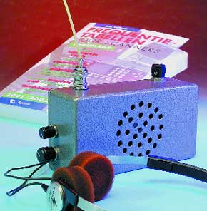
This receiver, specially designed for the VHF airband, couples decent performance to simple construction, all at an affordable price. It does not contain exotic parts and may be adjusted without special instruments, so we reckon the design makes an ideal entry-level receiver for aviation enthusiasts with two feet firmly on the ground.Eavesdropping on police, ambulance and fire brigade communications, to mention but a few examples, is a hobby with a persistent attraction to many. This has been the case ever since these services started using unprotected mobile communications. The exact reasons for the ‘addiction’ are hard to pinpoint. Curiosity, of course, but there’s more to it. A possible enticing factor is that scanner listening is somewhere in the twilight zone between ‘illegal’ and ‘allowed’, which no doubt adds to the excitement enjoyed by many scanner enthusiasts.
Materials
Gerber file
CAM/CAD data for the PCB referred to in this article is available as a Gerber file. Elektor GREEN and GOLD members can exclusively download these files for free as part of their membership. Gerber files allow a PCB to be produced on an appropriate device available locally, or through an online PCB manufacturing service.
Elektor recommends the Elektor PCB Service service from its business partner Eurocircuits or AISLER as the best services for its own prototypes and volume production.
The use of our Gerber files is provided under a modified Creative Commons license. Creative Commons offers authors, scientists, educators and other creatives the freedom to handle their copyright in a more free way without losing their ownership.
PCB
Component list
Resistors:
R1 = 220Ohm
R2 = 68kOhm
R3 = 330Ohm
R4 = 470Ohm
R5,R16,R25 = 1kOhm 8
R6,R21 = 1kOhm
R7,R14 = 5kOhm 6
R8 = 8kOhm 2
R9 = 39kOhm
R10 = 12kOhm
R11 = 47kOhm
R12 = 1kOhm 2
R13 = 22kOhm
R15 = 100kOhm
R17,R18 = 330kOhm
R19 = 150kOhm
R20 = 2kOhm 2
R22 = 560Ohm
R23 = 33kOhm
R24 = 47Ohm (1W)
R26 = 1kOhm 5
R27 = not fitted
R28 = 100Ohm
P1 = 50kOhm logarithmic potentiometer
P2 = 20kOhm multiturn
P3 = 100Ohm linear potentiometer.
Capacitors:
C1,C2 = 22pF
C3,C10,C13,C19,C21-C24,C27,C29,C38,C41 = 100nF
C4,C8,C9,C11,C15,C16,C33,C40 = 1nF
C5 = 18pF
C6 = 2pF2
C7,C43 = 15pF
C12 = 8pF2
C14 = 4pF7
C17,C44 = 22pF adjustable (trimmer)
C18 = 470µF 16V radial
C20 = 22µF 16V radial
C25 = 3nF3
C26 = 1nF8
C28,C42 = 10µF 16V radial
C30, C32 = 220µF 16V radial
C31 = 22nF
C34 = 68pF
C35,C36,C37 = 33pF
C39 = 5pF6
Semiconductors:
D1,D2 = BAT85
D3,D4 = KV1235
D5 = LED, red, high efficiency
D6 = 1N4001
D7 = LED, green, high efficiency
D8 = zener diode 6.2V, 0.4W
IC1 = SA612AN or NE612
IC2 = TCA440
IC3 = LM386
IC4 = LP2951CN
T1,T3,T4 = BFR91A
T2 = BC557
Miscellaneous:
BT1 = 9V battery (PP3) or 8 NiCd batteries (1.2V)
FL1 = 45M15AU
FL2 = SFR455H or -E (CFW455H or -E)
K1 = mains adaptor socket, PCB mount
L1,L2,L4,L8 = 100nH
L3 = 820nH
L5 = 560nH
L6 = LMC4101 (Toko)
L7 = 5 turns Æ 1mm silver-plated wire on Æ 5mm former (no core)
S1 = switch, 1 make contact
TR1 = 7MCS4718N (Toko)
X1 = 44.545MHz quartz crystal (case connected to ground)
LS1 = loudspeaker 8Ohm 1W
PCB, order code 010064-1 (see Readers Services pages)
Enclosure: e.g., BIM, dim. 150 x 80 x 50mm, order code 06.11.5005 (normal) of 06.11.5105 (enamel finish)
Many RF parts for this projects, including inductors, varicaps ceramic filters and trimmers are available from Barend Hendriksen HF Elektroni
Discussion (0 comments)