Article
LED Roulette
using LEDs instead of a ball
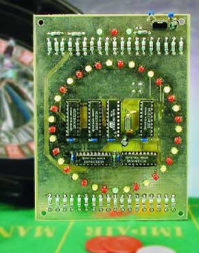
Everybody gambles sometimes, perhaps in a lottery or even in a casino. After all, who doesn’t dream of becoming rich without having to work hard? Although you can’t win much with the LED roulette wheel described here, it does provide an excellent opportunity to practice the game of roulette at home in an honest manner. That’s because you can’t cheat with this version - the microcontroller that controls the LEDs doesn’t take bribes!The game of roulette has been known for centuries, and it is played all over the world. In order to make it easier to play this game at home, here we a present an electronic roulette game. This electronic version only replaces the turntable, which is the dished wheel used with a small ball to select a random number for each round of the game. You will have to make the playing field and the counters yourself.
Materials
Gerber file
CAM/CAD data for the PCB referred to in this article is available as a Gerber file. Elektor GREEN and GOLD members can exclusively download these files for free as part of their membership. Gerber files allow a PCB to be produced on an appropriate device available locally, or through an online PCB manufacturing service.
Elektor recommends the Elektor PCB Service service from its business partner Eurocircuits or AISLER as the best services for its own prototypes and volume production.
The use of our Gerber files is provided under a modified Creative Commons license. Creative Commons offers authors, scientists, educators and other creatives the freedom to handle their copyright in a more free way without losing their ownership.
PCB
Extra info / Update
The PCB has a short-circuit between the anode of D18 and the +5 V rail. To lift the short-circuit, two tracks have to be cut and a wire link fitted.
Component list
Resistors:
R1-R40 = 1kOhm
R41-R43 = 10kOhm
Capacitors:
C1,C2 = 22pF
C3-C10 = 100nF
C11 = 10µ F 16V radial
C12 = 1µ F 16V radial
Semiconductors:
D1,D38,D40 = LED, 3mm, green, low current
D2,D4,D6,D8,D10,D12,D14,D16,D18,D20,D22,D24,D26,D28,D30,D32,D34,D36,D39 = LED, 3mm, yellow, low current
D3,D5,D7,D9,D11,D13,D15,D17,D19,D21,D23,D25,D27,D29,D31,D33,D35,D37 = LED, 3mm, red, low current
IC1 = 89C2051-12PC, programmed, order code 030168-41
IC2-IC6 = 74HCT373
IC7 = 7805CP (TO-220 case)
Miscellaneous:
K1 = 9V battery with clip and on/off switch (optional)
S1 = pushbutton with make contact
S2 = on/off switch
X1 = 12MHz quartz crystal
PCB, order code 030168-1
Disk, contains source and hex code files, order code 030168-11 or Free Download
Discussion (0 comments)