Article
FM Stereo Test Transmitter
VHF FM and audio test signals
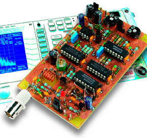
This small signal generator uses an ingenious technique to generate a sine wave with very low distortion, a mono (L+R) baseband signal and an FM stereo signal.
Materials
Gerber file
CAM/CAD data for the PCB referred to in this article is available as a Gerber file. Elektor GREEN and GOLD members can exclusively download these files for free as part of their membership. Gerber files allow a PCB to be produced on an appropriate device available locally, or through an online PCB manufacturing service.
Elektor recommends the Elektor PCB Service service from its business partner Eurocircuits or AISLER as the best services for its own prototypes and volume production.
The use of our Gerber files is provided under a modified Creative Commons license. Creative Commons offers authors, scientists, educators and other creatives the freedom to handle their copyright in a more free way without losing their ownership.
PCB
Component list
Resistors
R1 = 1k
R2 = 1M
R3 = 470k
R4 = 180k
R5 = 15k
R6,R27 = 100k
R7 = 39k
R8 = 2k4 (or 2k43 from E96 series)
R9,R10,R25,R26,R28,R29 = 10k
R11 = 5k1 (or 5k11 from E96 series)
R12,R13 = 120k
R14 = 47k
R15 = 1k8
R16, R18 = 22k
R17 = 1k5
R19 = 33
R20 = 2k2
R21 = 4k7
R22 = 68
R23 = 470
R24 = 56
R30 = 5k6
R31 = 330
R32 = 100
R33 = 820
P1 = 25k preset
P2 = 4k7 preset
Capacitors
C1 = 47pF
C2 = 56pF
C3 = 22nF MKT, lead pitch 5mm
C4,C9,C13,C15,C26-C30,C32 = 100nF ceramic, lead pitch 5mm
C5,C10 = 47µF 6V3 tantalum or radial electrolytic
C6,C12 = 68pF
C7 = 4nF7 MKT lead pitch 5mm
C8,C16,C17,C21-C25 = 1nF, lead pitch 5mm
C11 = 4µF7 16V tantalum or radial electrolytic
C14 = 220µF 10V radial
C18 = 18pF
C19 = 100pF
C20 = 22pF PTFE trimmer capacitor
C31 = 4µF7 16V radial
Inductor
L1 = 6 turns 0.8mm ECW or CuAg, internal diameter 5mm
Semiconductors
D1,D2,D5 = 1N4148
D3,D4 = BB405 (alternatives: BB205, BB505, BB208-03)
D6 = LED, red, low current
T1 = BF199
IC1 = 74HC4060
IC2,IC3 = 74HC86
IC4 = TLC277 (TS922IN)
IC5 = 74HC4066
IC6 = 78L05
Miscellaneous:
JP1 = 2-way pinheader w. jumper
S1 = on/off switch (and/or 2-way pinheader w. jumper)
S2 = 1-pole, 3-way switch (and/or 3-way pinheader w. jumper)
S3, S4 = changeover switch (and/or 3-way pinheader w. jumper)
X1 = 9.728MHz quartz crystal, HC-49/U, fundamental frequency, parallel resonance, load capacitance 30 pF, ±10 ppm, (see text)
BT1 = 9V battery with clip-on leads
BNC socket 50 Ohm (optional)
PCB, order code 050268-1
Discussion (0 comments)