Article
RC Servo Tester/Exerciser
-
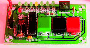
The design presented here is for a device for testing radio control (RC) servos. The present design has features that make it especially useful to people designing and building radio control equipment. By building a number of these devices in a single enclosure an entire radio controlled model can be set up and tested without having to actually use the RC transmitter.
The most unusual feature of this design is that it doesn’t use a joystick or similar analogue device to determine the servo position. Instead it gives an output of precisely 1.5 ms that can be changed up or down in steps of 0.166 ms and gives a display on a line of LEDs of the position selected.
Materials
Gerber file
CAM/CAD data for the PCB referred to in this article is available as a Gerber file. Elektor GREEN and GOLD members can exclusively download these files for free as part of their membership. Gerber files allow a PCB to be produced on an appropriate device available locally, or through an online PCB manufacturing service.
Elektor recommends the Elektor PCB Service service from its business partner Eurocircuits or AISLER as the best services for its own prototypes and volume production.
The use of our Gerber files is provided under a modified Creative Commons license. Creative Commons offers authors, scientists, educators and other creatives the freedom to handle their copyright in a more free way without losing their ownership.
PCB
Component list
Resistors
(1/4W 10%)
R1,R4,R5,R6 = 10k
R2, R3=1k
Capacitors
(5mm lead pitch)
C1,C2 = 27pF
C3, C4 = 100nF
D1,D2,D3,D5,D6,D7 = LED, 3mm, high efficiency, green
Semiconductors
D4, D8 = LED, 3mm, high efficiency, yellow
IC1 = PIC16F84(A), DIL18 case, programmed, order code 040172-41
IC2 = LM2940, TO220 case (or 5V 1A low drop equivalent)
Miscellaneous
X1 = 8MHz quartz crystal, 32pF parallel load capacitance, HC49 case or low-profile model
K1 = 3 way SIL pinheader
S1, S2, S3 = pushbutton, 1 make contact
Case: Hammond 1591ATBU
IC socket 18p
Mains adaptor DC socket
PCB, order code 040172-1
Project software, free download 040172-11 from Elektor website
A kit of parts is available from Elektor Electronics; order code 040172-71, see SHOP pages or website. Kit contents as components list.
Discussion (0 comments)