Article
A Simple Mains Inverter
12 VDC in, 230 VAC out
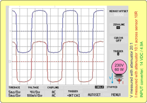
Circuits that convert a DC supply into a 50 Hz AC supply are called inverters. Commercial units are notable for their small size, high efficiency and high power output. A simpler approach using a standard mains transformer is however more than adequate to power a TV set and satellite receiver from a 12 V vehicle battery.
Materials
Gerber file
CAM/CAD data for the PCB referred to in this article is available as a Gerber file. Elektor GREEN and GOLD members can exclusively download these files for free as part of their membership. Gerber files allow a PCB to be produced on an appropriate device available locally, or through an online PCB manufacturing service.
Elektor recommends the Elektor PCB Service service from its business partner Eurocircuits or AISLER as the best services for its own prototypes and volume production.
The use of our Gerber files is provided under a modified Creative Commons license. Creative Commons offers authors, scientists, educators and other creatives the freedom to handle their copyright in a more free way without losing their ownership.
PCB
Extra info / Update
- Replaced 74HCT ICs (7 V) by CMOS types (15 V)
- Consequently the two npn driver transistors are omitted.
- 3.9-volt zener diode inserted in the gate lines of the power MOSFETs. These create a voltage gap to prevent both MOSFETs conducting simultaneously during switchover.
- Added snubber network (R9/C7 is updated schematic).
- Added mains voltage caution in circuit diagram.
The download (left) contains the updated circuit diagram in pdf format and the corrected PCB artwork with all files (schematic, layout, components in .bmp, .jpg and .ps format), as well as the original Eagle files supplied by the author and datasheets from the semiconductor manufactures.
Component list
Resistors
R1 = 1 MΩ
R2 = 1 kΩ
R3..R6 = 2kΩ2
R7,R8 = 100 Ω
Capacitors
C1 = 47 pF
C2 = 27 pF
C3,C4 = 100 nF
CE1 = 2200 µF 25 V
C7 = 330 nF
Halbleiter:
IC1 = 4060
IC2 = 4027
Q1, Q2 = BC547B
V1, V2 = IRF4905
V3, V4 = IRF3205
ZD1-ZD4 = 3.9 V/0.5 W (zener diodes)
Miscellaneous
ST1, PL1 = 2-way PCB terminal block, PCB mount
XT1 = 3.2768MHz quartz crystal
Mains transformer, 1x12V or 2x12V secondary, 50-200VA
15-A fuse with holder in 12-V supply lead
PCB (Layout in free download 060171 update.zip)
Discussion (0 comments)