Article
Microlight Fuel Gauge
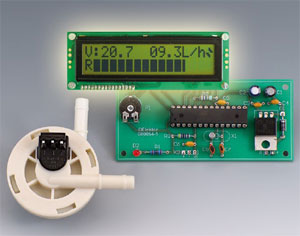
The design of this measuring instrument was based on thse requirements:
- a microlight always takes off with the fuel tank full; – fuel consumption is usually between 7 and 9 litres/hour; – it’s important for the gauge to be perfectly readable in all circumstances, e.g. in the form of a bargraph; – an indication of the amount of fuel remaining, expressed in litres;– an indication of the instantaneous fuel consumption (l/h); – it must be possible to have complete confidence in the gauge, so provision needs to be made for a warning in the event of it going wrong; All requirements are catered for by the present design.
Materials
Gerber file
CAM/CAD data for the PCB referred to in this article is available as a Gerber file. Elektor GREEN and GOLD members can exclusively download these files for free as part of their membership. Gerber files allow a PCB to be produced on an appropriate device available locally, or through an online PCB manufacturing service.
Elektor recommends the Elektor PCB Service service from its business partner Eurocircuits or AISLER as the best services for its own prototypes and volume production.
The use of our Gerber files is provided under a modified Creative Commons license. Creative Commons offers authors, scientists, educators and other creatives the freedom to handle their copyright in a more free way without losing their ownership.
PCB
Component list
Resistors
R1 = 1kOhm
R2 = 33Ohm
R3 = 4kOhm7
P1 = 10 kOhm preset
Capacitors
C1 = 220µF 25V
C2 = 10µF 25V
C3-C6 = 100nF
C7,C8 = 22pF
Semiconductors
D1 = 1N4004
D2 = LED, red
IC1 = 7805
IC2 = ATMEGA8, programmed with hex file from archive 080054-11.zip
Miscellaneous
X1 = 32.768 kHz quartz crystal
K1 = 2-way pinheader
K2 = 16-way SIL pinheader
K3 = 3-way pinheader
LCD, 2 x 16 characters with backlight, general purpose
F1 = flow meter, Digmesa type FHKSC 932-8501 (Conrad Electronics)
PCB, ref. 080054-1 from www.thepcbshop.com
Discussion (0 comments)