Article
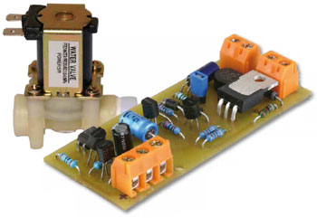
A Zero Current Switch for Inductive Loads

Relays or contactors are often used to switch AC-powered inductive loads such as motors, valves or electro magnets. When the device is switched off, an arc can form across the relay contacts as they open. This leads to premature relay failure if measures are not taken to suppress the spark.
Materials
Gerber file
CAM/CAD data for the PCB referred to in this article is available as a Gerber file. Elektor GREEN and GOLD members can exclusively download these files for free as part of their membership. Gerber files allow a PCB to be produced on an appropriate device available locally, or through an online PCB manufacturing service.
Elektor recommends the Elektor PCB Service service from its business partner Eurocircuits or AISLER as the best services for its own prototypes and volume production.
The use of our Gerber files is provided under a modified Creative Commons license. Creative Commons offers authors, scientists, educators and other creatives the freedom to handle their copyright in a more free way without losing their ownership.
PCB
Component list
Resistors
R1 = 100 Ohm
R2 = 2.2kOhm
R3,R4 = 47kOhm
R5 = 82kOhm 1%, 0.6W 350V (Vishay MRS25000C8202FCTOO)
R6 = 220Ohm
R7 = 180Ohm
R8 = 68Ohm
R9 = 22kOhm
Capacitors
C1,C3 = 10µF 100V 20%, pitch 2.5mm, diam. 6.3mm
C2 = 10µF 63V, axial, 10 x 4.5mm
Semiconductors
D1,D2 = 1N4004
D3 = 1N4007
D4 = BZX79-C13 (13V 05W)
B1 = WO6M, 600V 1.5A
T1 = IRG4BC3OKDPbF
T2..T5 = BC546A
IC1 = PC817 (see text)
Miscellaneous
PCB # 100270


Discussion (5 comments)