Do you need a multifunction frequency meter for making time-related measurements? Take a look at this user-friendly design from 2004. It’s a creative solution that offers a wide range of measurement options.
Do you need a multifunction frequency meter for making time-related measurements? Take a look at this user-friendly design from 2004. It’s a creative solution that offers a wide range of measurement options.
Frequency Meter Circuit
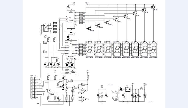
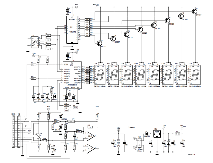
Let's begin with the Multifunction Frequency Meter circuit. The circuit's functional elements include an AT90S microcontroller, readout, mode switch, signal conditioning and voltage supply.
Frequency meter circuit
"The micro is clocked at a frequency of 10 MHz and offers no fewer than 15 configurable I/O lines divided across two ports," the designer R. Zenzinger noted. "The lines in Port B are all programmed as outputs, driving the individual segments of the 7-segment displays. By contrast, the lines in Port B have different functions, acting as inputs or outputs. Only PD0 and PD4 are invariably output lines with their internal pull-up resistor (approx. 50 kΩ) activated. PD.1, PD.2 and PD.3 are only active after a reset or when a different measurement mode is selected on the rotary switch. During operation, output mode is selected in order to drive the display."
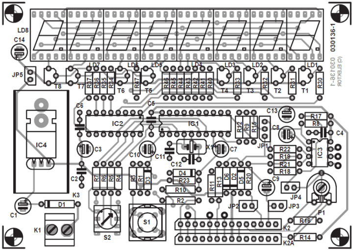
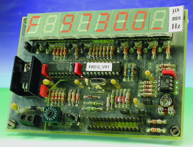
A double-sided board enables the versatile instrument to be built in a very compact way.
A double-sided board allows the versatile instrument to be built in a compact way.
When the instrument is housed in a stylish ABS enclosure, the controls should be relocated from the board to the front panel. Using a case with a transparent cover, such as a Teko type P3 or P4, can significantly reduce the need for tooling since no cutouts are required for the LED display. You simply need to mount the displays in stacked sockets.
Frequency Meter Specs
Consider with the design's features and specs:
Frequency measurement using 3 gate times
Period duration measurement in milliseconds and microseconds
Pulse duration measurement of positive and negative half cycles in milliseconds and microseconds
Event counter up to 107 events
Stopwatch with lap time function; resolution 10 ms
8-digit 7-segment LED readout
Selectable pause of 1-5 s or manual restart
Resolution 0.1 microsecond or 0.1 second
4 MHz maximum input frequency
1 microsecond minimum pulse length
1,000 s maximum pulse length
10 mV – 5 V input voltage range protected up to 30 V (higher swings possible by adding an external voltage divider)
The article, “Multifunction Frequency Meter: For All Time-Related Measurements,” was published in Elektor March 2004. The article will be free to download for at least the two weeks after the publication of this news item. Enjoy the article!
Editor's Note: This article was first published in a 2004 edition of Elektor magazine. Please note that some of the components, products (e.g., PCBs) and links may no longer be available. However, we believe the educational content remains valuable and hope it inspires you to start new projects.
Subscribe
Tag alert: Subscribe to the tag Circuits & Circuit Design and you will receive an e-mail as soon as a new item about it is published on our website!
Read full article
Hide full article
Add a rating to this article
★★★★★
★★★★★
Page 1 / 1
Login
No account yet?Register for free!
Forgot password?
Please enter your email address. Instructions for resetting the password will be emailed to you now.


Discussion (1 comment)