Error Analysis: All Components Are Suspect
October 20, 2020
on
on

Looking for tips about printed circuit board (PCB) design? Chris Clapham is an Auckland, New Zealand-based hardware engineer with 30+ years of experience working with PCBs. He offers some great advice: always check your components. Even new components can be faulty.

The Elektor team wants to hear about your electronics-relate errors and learnings. Fill out our "Error Analysis" form and share your experience. Professional engineers, makers, and technical students are welcome to contribute!
Check your components
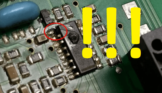
“Never remove brand new components from the suspect list! While working for a TV PCB reconditioning company 30-plus years ago — where we not only repaired faulty PCBs, but they were reconditioned, electrolytics replaced, dry joints resoldered, etc., and any stressed looking components replaced — we came across a few faulty but brand new components. These included transistors with their complementary device in the package or their marking switched (not sure which) — that is, a PNP in a case with an NPN part number, efficiency diodes that measured nearly identical to a good one but did not work properly leaving the power supply to run very hot. We even had a diode which had the anode and cathode swapped. The device the TV manufacture had used (they got them cheap) had the cathode connected to the metal tab (TO-220 type case from memory) and that was connecting to the heatsink, which was grounded (no insulator) but the new part (correctly made) had the anode connected to the tab, so it shorted when fitted until you figured out that it needed a mica washer to make it work. Field techs would replace the shorted original and then not be able to figure out why the board was still faulty. If they took out the new diode, it measured fine. And the other diode incident was a DO-201 packaged diode. The shorted diode on the PCB was replaced, yet the board would not work. After checking everything several times over and getting advice from a work mate, we noticed that when compared to a working PCB the meter leads had to be swapped to get the diode to conduct. The Diode was in the PCB the same way around but the junction inside the case was reversed. So now I know that I need to check that the diode not only conducts one way and not the other, but also it must be in the circuit the right way (despite the case or PCB marking ).” — Chris Clapham
More on PCBs, PCB Design, and Prototyping
Want tips and insights about PCB design, prototyping, and more? Consider these resources:- Elektor TV, “PCB Layout with Pcbnew," 6/5/2020.
- C. Valens, "More 3D Libraries for KiCad EDA," Elektor, 10/7/2019.
- Elektor, "ElektorPCB4Makers: Your Affordable, Environmentally-Friendly PCB Service," 1/23/2020.
- Read about KiCad Plugins and Add-ons
- Read about Schematic Capture with Eeschema
The Elektor team wants to hear about your electronics-relate errors and learnings. Fill out our "Error Analysis" form and share your experience. Professional engineers, makers, and technical students are welcome to contribute!
Read full article
Hide full article


Discussion (0 comments)