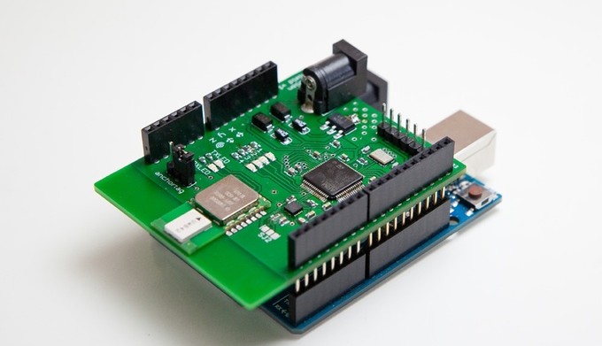
Pozyx Shield Gives Position
June 04, 2015
on
on

Resolving the position of free roaming robots can be quite challenging. You can only expect to get accuracy of around 6 to 10 meters by using a standard low-cost GPS system and that can be further downgraded by poor signal strength inside buildings. Bluetooth and WiFi positioning can achieve 1 to 5 metres resolution but that’s often not enough. The Pozyx system has been developed to achieve a positional accuracy of 10 cm and works indoors or outdoors.
Four ‘Anchor’ transceiver units attach to walls or fences surrounding the space in which the Pozyx Shield operates. Communication between the shield and the four anchors allows the shield to determine its position and orientation within its operational area.
Key components on the shield include:
• An STM32F401 microcontroller
• Ultra-wideband transceiver (decawave DWM1000)
• 9-axis inertial motion unit (invensense MPU9250)
• Pressure sensor (freescale MPL3115A2)
• I2C for serial communication
• SWD for programming
• Micro USB for firmware updates
• 4 general purpose LEDs
• 2 LEDs for UWB connectivity
• 4 optional GPIO pins
• Onboard 3.3V regulator: automatic power selection from battery, arduino or usb.
Although the shield will fit happily on an Arduino board it can also operate with other systems such as the Raspberry Pi where it can communicate via an I2C interface. The maximum (line of sight) range of the shield to an anchor point is around 200 m which makes it suitable for quite large spaces. The system has been recently launched for funding on Kickstarter.
Read full article
Hide full article


Discussion (1 comment)