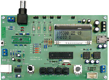
The Elektor DSP radio (1)
DSP world receiver with USB interface

Materials
Gerber file
CAM/CAD data for the PCB referred to in this article is available as a Gerber file. Elektor GREEN and GOLD members can exclusively download these files for free as part of their membership. Gerber files allow a PCB to be produced on an appropriate device available locally, or through an online PCB manufacturing service.
Elektor recommends the Elektor PCB Service service from its business partner Eurocircuits or AISLER as the best services for its own prototypes and volume production.
The use of our Gerber files is provided under a modified Creative Commons license. Creative Commons offers authors, scientists, educators and other creatives the freedom to handle their copyright in a more free way without losing their ownership.
Extra info / Update
- no set-up adjustments required
- Si4735 DSP receiver IC
- ATmega168 microcontroller
- USB interface using FT232R
- backlit 2 x 16 LCD panel
- battery voltage 4.8 to 6 V
- current consumption approximately 50 mA
- 3.3 V internal power supply
- power from PC over USB interface
- stereo audio output
- stereo audio amplifier (2 x LM386)
- RDS display
- AM from 153 kHz to 21.85 MHz
- automatic station search
- antenna signal strength indication in dBµV
- signal strength meter connection
- diode switching of AM band
- automatic tuning of AM resonant circuit
- switchable AM bandwidth
- optional PC control over USB
- tuning using rotary encoder
- four control pushbuttons
- station memory (30 AM presets and 30 FM presets)
- open-source firmware (free download)
- in-system programming interface
- printed circuit board available ready-populated and tested
Components
The BOM (Bill of Materials) is the technically exhaustive listing of parts and other hardware items used to produce the working and tested prototype of any Elektor Labs project. The BOM file contains deeper information than the Component List published for the same project in Elektor Magazine. If required the BOM gets updated directly by our lab engineers. As a reader, you can download the list here.
Want to learn more about our BOM list? Read the BOM list article for extra information.
Component list
(5%, 0.25 W)
R1-R3 = 100Ohm
R4,R5 = 470Ohm
R6-R8 = 22kOhm
R9,R10 = 1kOhm
R11 = 47Ohm
R12,R13 = 10Ohm
P1 = 10kOhm trimpot, linear, vertical adjustment, PCB mount, ALPS type RK09K11310KB (Farnell # 1191725)
Capacitors
C1,C23,C24,C26,C27 = 1uF 16V, electrolytic, radial, 5mm diameter
C2, C3 = 4.7uF 16V, electrolytic, radial, 5mm diameter
C4-C16 = 100nF, ceramic capacitor, 2.54 mm lead pitch
C17, C18 = 47pF, ceramic capacitor, NP0, 5.08mm lead pitch
C19, C20 = 22pF, ceramic capacitor, NP0, 5.08mm lead pitch
C21, C22 = 12pF, ceramic capacitor, NP0, 5.08mm lead pitch
C25 = 100uF 16V, electrolytic, radial, 6.3mm diameter
C28, C29 = 47uF 16 V, electrolytic, radial, 6.3mm diameter
C30, C31 = 470uF 16 V, electrolytic, radial, 8.0mm diameter
C32, C33 = 100nF, polyester (MKT), 5.08 mm lead pitch
Inductors
L1 = 10uH (Fine Inductors Fastron type SMCC-100X-YY)
L2 = 0.1uH (Fine Inductors Fastron type SMCC-R10X-YY)
L3 = 4.7uH (Fine Inductors Fastron type SMCC-4R7X-YY)
L4 = 220uH (Fine Inductors Fastron type SMCC-221X-YY)
L5 = 2.2mH (Fine Inductors Fastron type SMCC-222X-YY)
Semiconductors
D1-D5 = BAT48, Schottky diode, 330 mW, DO-35
D6,D7 = 1N4148
IC1 = LP2950ACZ-3.3/NOPB, LDO voltage regulator, 3.3 V, 100 mA, TO-92
IC2 = FT232RL, USB to serial UART interface, FTDI, SSOP-28
IC3 = ATmega168PA-PU, PDIP-28, programmed, Elektor # 100126-41)
IC4, IC5 = LM386N-1, DIL-8
Y1 = Si4735 broadcast AM/FM/SW/LW radio receiver carrier board, DIL-20, Elektor # 090740-71
Miscellaneous
ENC1 = Rotary encoder, vertical, 12 ppr, ALPS type EC12E1220401 (Farnell # 1520809)
JP1 = 3-way pinheader, 2.54 mm lead pitch + jumper
JP2-JP5 = 2-way pinheader, 2.54 mm lead pitch + jumper
K1-K3 = 2-way, screw-type terminal block, 5mm lead pitch
K4 = BNC connector 50 ohms, black, PCB, mount, Tyco Electronics type 1-1634612-0 (right angle);
type 1-1634505-0 (vertical) (Farnell # 1020957; # 1020960)
K5 = 3-way PCB terminal block, 5mm lead pitch
K6 = jack socket, 3.5mm, stereo (Farnell # 1267400)
K7 = USB socket type B, PCB mount
K8 = 6-way (2x3) header, wire-to-board (Farnell # 1096984)
LCD1 = Alphanumeric LCD 2x16, (Electronic Assembly type EA DOGM162W-A) + LED blue backlight (type EA LED55X31-B)
S1 = slide switch, SPDT, C&K type OS102011MS2QN1 (Farnell # 1201430)
S2-S5 = Tactile switch, SPNO, MULTIMEC type 3FTL6 (Farnell # 1132885) + elevation caps
X1 = 8MHz quartz crystal, low-profile, case type HC49
X2 = 32.768 kHz quartz crystal, cylindrical case (3x8 mm)
2 pcs IC socket, DIL-8
1 pc IC socket, DIL-28 narrow body
Sockets for LCD elevation
PCB, bare, Elektor # 100126-1
PCB ready assembled and tested, Elektor # 100126-91


Discussion (0 comments)