

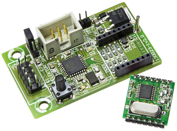
Wireless Gateways
From serial to radio, and back again
Gerber file
CAM/CAD data for the PCB referred to in this article is available as a Gerber file. Elektor GREEN and GOLD members can exclusively download these files for free as part of their membership. Gerber files allow a PCB to be produced on an appropriate device available locally, or through an online PCB manufacturing service.
Elektor recommends the Elektor PCB Service service from its business partner Eurocircuits or AISLER as the best services for its own prototypes and volume production.
The use of our Gerber files is provided under a modified Creative Commons license. Creative Commons offers authors, scientists, educators and other creatives the freedom to handle their copyright in a more free way without losing their ownership.
Components
The BOM (Bill of Materials) is the technically exhaustive listing of parts and other hardware items used to produce the working and tested prototype of any Elektor Labs project. The BOM file contains deeper information than the Component List published for the same project in Elektor Magazine. If required the BOM gets updated directly by our lab engineers. As a reader, you can download the list here.
Want to learn more about our BOM list? Read the BOM list article for extra information.
Component list
Resistors
R1,R4 = 1kOhm (0805)
R2 = 10kOhm (0805)
R3 = 2kOhm (0805)
R5,R7,R9,R11,R13,R15,R17,R19 = 1.8kOhm (0603)
R6,R8,R10,R12,R14,R16,R18,R20 = 3.3kOhm (1%, 0603)
Capacitors
C1,C2 = 22pF (0805)
C3..C7 = 100nF (0805)
C8 = 4.7µF (0805)
C9 = 10µF, 25V (1206)
C10,C11 = 1µF (0603)
Semiconductors
D1 = LED yellow (0805)
D2 = LED green (0805)
D3 = PMEG2010AEH Schottky diode (SOD-123F)
IC1 = ATmega328P-AU, programmed (TQFP-32)
IC2 = LDO NCP5501DT50G (DPAK-3)
IC3 = XC6206P332MR (SOT-23-3)
Miscellaneous
K1 = 10-pin (2x5) pinheader, 0.1’’ pitch
K2 = 6-pin (2x3) pinheader, 0.1’’ pitch
K3 = 2-pin pinheader, 0.1’’ pitch
JP1 = 3-pin pinheader, 0.1’’ pitch with jumper
S1 = pushbutton
X1 = 16MHz quartz crystal, 50ppm, 18pF
MOD1 = RFM12B-433-S1 radio module (HopeRF)
14-pin pinheader, 2mm lead pitch
14-way receptacle. 2mm pitch
PCB # 130023-1
We buy at:

Discussion (0 comments)