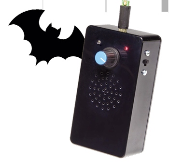
Bat DetectorPLUS
Combines frequency division with amplitude recovery

This is a MEMBER ONLY article. You need a subscription to read this article.
- Access to Elektor archive and 5,000+ Gerber files
- Receive up to 8 magazines per year (digital and/or paper)
- 10% discount in the Elektor store
Available from €4.95 per month.
What is Members Only
Elektor is committed to providing high-quality content on electronics, catering to tens of thousands of paying members. As part of this commitment, Elektor has launched Premium, an initiative that offers exclusive online articles to members sometimes even before they appear in the magazine.
Every day, members can access in-depth articles that showcase the best of Elektor's premium content.
This initiative aims to reward members with early access. Once logged in, members can easily enjoy this exclusive content and engage in discussions about featured projects. While Premium adds to the existing resources available, Elektor will continue to provide a wealth of free information.
Join the Elektor community today to take advantage of Premium and other benefits!
Gerber file
CAM/CAD data for the PCB referred to in this article is available as a Gerber file. Elektor GREEN and GOLD members can exclusively download these files for free as part of their membership. Gerber files allow a PCB to be produced on an appropriate device available locally, or through an online PCB manufacturing service.
Elektor recommends the Elektor PCB Service service from its business partner Eurocircuits or AISLER as the best services for its own prototypes and volume production.
The use of our Gerber files is provided under a modified Creative Commons license. Creative Commons offers authors, scientists, educators and other creatives the freedom to handle their copyright in a more free way without losing their ownership.
Extra info / Update
- Hybrid analog and digital circuitry
- Low current consumption: less than 5 mA in standby
- Selectable division ratio: 16, 17, 23 and 31
- Selectable low frequency cut-off: 8 kHz, 15 kHz, 18 kHz 25 kHz
- Selectable sensitivity verses battery saving
- Improved amplitude recovery
- Audio sinewave output
- Audio amplifier muted and in standby mode when there is no input signal
- ‘Muted’ and ‘signal detected’ LEDs
- Hardware and software test mode
- MEMS or electret microphone
- 1 (one) SMD device
Component list
Main Board
Resistors
R1,R2,R24,R29,R34 = 47kΩ 5%, 0.25W, 250V
R3,R30,R32 = 4.7 kΩ 5%, 0.25W, 250V
R4,R7,R10 = 7.5kΩ 1%, 0.6W, 350V
R5,R8,R11,R13,R14,R16-R18,R20,R21,R25-R28,R33 = 10kΩ 5%, 0.25W, 250V
RR6,R9,R22 = 100kΩ, 5%, 0.25W, 250V
R12 = 82kΩ 5%, 0.25W, 250V
R15 = 30kΩ 5 %, 0.33W, 250V
R19 = 36kΩ 5 %, 0.33W, 250V
R23 = 1MΩ 5%, 0.25W, 250V
R31 = 39kΩ 5%, 0.25W, 250V
R35 = 100Ω 5%, 0.25W, 250V
P1 = 50kΩ 10%, 0.5W, trimmer, 23-turn
P2 = 100kΩ 10%, 0.5W, trimmer, 23-turn
P3 = 10kΩ 20%, 0.2W, rotary potentiometer, logarithmic law, with switch, single
Capacitors
C1 = 220µF 20%, 50V, 5mm pitch, 10x16 mm
C2,C3,C6,C7,C8,C11,C22,C23 = 100nF 10%, 50V, X7R, 0.2’’ pitch
C4 = 100µF, 20%, 50V, 3.5mm pitch, 8x11 mm
C5,C9,C10,C24 = 10µF 20%, 50V, 2mm pitch, 5x11 mm
C12,C14,C16,C21 = 1nF 5%, 100V, C0G/NP0, 0.2’’ pitch
C13,C15,C17 = 4.7pF ±2.5pF, 500V, NP0, 5.08mm pitch
C18 = 470pF 5%, 100V, C0G/NP0, 0.2’’ pitch
C19,C20,C25,C26,C28 = 10nF, 10%, 100V, X7R, 0.2’’ pitch
C27 = 47µF, 50V, 2.5mm pitch, 6.3x11 mm
Semiconductors
D1,D2 = BAT43, DO-35
D3 = BZX79-C3V0, 3V zener diode, 0.5W, DO-35
LED1 = blue, 3mm, high intensity
LED2 = red, 3mm, high intensity
T1,T2,T4,T5 = BC548B
T3 = BC558B
IC1 = TL061CP, DIP-8
IC2,IC3,IC4 = TL062CP, DIP-8
IC5 = LP2950ACZ-5.0, LDO, 5V, 0.1A, TO-92
IC6 = PIC16F1827-I/P, DIP-18, programmed, Elektor Store # 150346-41
IC7 = TDA8541T/N1, SMD SOIC-8, Newark/Farnell # 1854043
Miscellaneous
K1 = 4-pin pinheader, vertical, 0.1’’ pitch
K2,LED1,LED2,LS1 = Pin header, 1x2, vertical, 0.1’’ pitch
BT1 = 2-way PCB screw terminal block 0.2’’ mm, 630V
TP1,TP2,TP3 = 1 pin from pinheader
S1 = 8-way DIP switch block
BT1 = battery retainer clip (for battery PP3, 9V) with wires
Enclosure, ABS, 40x65x120mm, Camdenboss BIM2004/14-BLK/BLK, Newark/Farnell # 2445837
LS1 = miniature loudspeaker, 8Ω, >0.5W
MIC. = phone audio connector, socket, 3.5mm, 3 contacts, panel mount
PCB, Elektor Store # 150346-1
Kit of parts, includes PCB, case and MEMS board 150346-91. Elektor Store # 150346-71
Component List
MEMS Microphone Board
Capacitor
C1 = 100nF 5%, 25V, C0G/NP0, SMD 1206, optional
Miscellaneous
MIC1 = MEMS Microphone SPU0410HR5H-PB (Knowles), Mouser # 721-SPU0410HR5H-PB
K1 = connections for wires or pinheader
Phone Audio Connector, Plug, 3.5mm, 3 contacts, Cable Mount
PCB, Elektor Store # 150346-2
Ready assembled MEMS microphone board, Elektor Store # 150346-91


Discussion (0 comments)
NickT 6 years ago
K. Horton 6 years ago
NickT 6 years ago
Elektor kits used to set a standard, but these days, the only standard that they set is a bad one - very sad.
mfc 5 years ago
Evidence: http://speleogroup.org/files/2019/Bat-kit-components.jpg :-)