Article
Elektor SDR Reloaded (1)
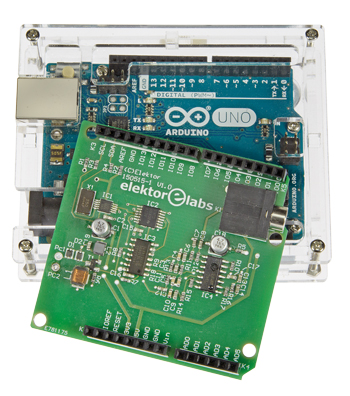
SDR Shield for the Arduino

A Software Defined Radio is a universal tool in RF technology circles, one that can also be put to use for making measurements. The characteristics of the receiver are defined in software, which now gives us the opportunity to use an Arduino Shield as a front-end.
Gerber file
CAM/CAD data for the PCB referred to in this article is available as a Gerber file. Elektor GREEN and GOLD members can exclusively download these files for free as part of their membership. Gerber files allow a PCB to be produced on an appropriate device available locally, or through an online PCB manufacturing service.
Elektor recommends the Elektor PCB Service service from its business partner Eurocircuits or AISLER as the best services for its own prototypes and volume production.
The use of our Gerber files is provided under a modified Creative Commons license. Creative Commons offers authors, scientists, educators and other creatives the freedom to handle their copyright in a more free way without losing their ownership.
PCB
Extra info / Update
Supply voltage: 5 V and 3.3 V as for Arduino
Frequency range: 150 kHz up to 30 MHz
Sensitivity: 1 µV
Total amplification: 40 dB
Maximum antenna signal level: 10 mV
Dynamic range: 80 dB
Frequency range: 150 kHz up to 30 MHz
Sensitivity: 1 µV
Total amplification: 40 dB
Maximum antenna signal level: 10 mV
Dynamic range: 80 dB
Component list
Component List
Resistors
R1,R2,R13,R18 = 4.7kOhm 1%, 0.1W, SMD 0603
R3,R4 = 330Ohm 1%, 0.1W, SMD 0603
R5,R7,R8 = 100Ohm 1%, 0.1W, SMD 0603
R6 = 470 Ohm 1%, 0.1W, SMD 0603
R9,R11,R14,R16 = 10kOhm 1%, 0.1W, SMD 0603
R10,R12,R15,R17 = 100kOhm, 0.1W, SMD 0603
Capacitors
C1,C18 = 4.7µF 16V, SMD case B
C2,C3,C6,C7,C8,C9,C12,C13,C14,C15,C16,C17,C19 = 100nF 50V, X7R, SMD 0603
C4,C5,C10,C11 = 2.2nF 50V, X7R, SMD 0603
Inductors
L1 = 2200µH (Fastron L-1812AF)
L2 = 100µH (Murata LQH32CN101K23L)
Semiconductors
D1,D2 = 1N4148WS, SOD-323
T1 = BF545B, SOT-23
IC1 = SI5351A-B-GT, MSOP-10
IC2 = SN74AC74PW, TSSOP-14
IC3 = 74HC4066, SOIC-14
IC4 = TI914IDT, SOIC-14
Miscellaneous
K1 = stereo jack socket, 3.5mm, PCB mount
K2,K3,K4,K5 = connector set, Arduino compatible (1 pc. 6-pin, 2 pcs. 8-pin, 1 pc. 10-pin)
X1 = 25MHz quartz crystal (Abracon ABM7)
PCB # 150515-1
Or
PCB with preassembled SMD parts: 150515-91


Discussion (0 comments)
marioc 8 years ago
I've found the article very interesting.
Did you already measure the noise figure of this receiver ?
If so could you please reply here or add it to the product description?
thank you,
mario
Antony Watts 8 years ago
ZQ.Fan 5 years ago
Jeff Wandling 2 years ago
We have the BOM (parts list), which is wonderful, but the schematic would be very useful.
The assembled boards are out of stock, but the parts on the board -- I have them. Just not the schematic..
Please consider posting the schematic, that would be wonderful. Thank you.
-jeff
ElektorLabs 1 year ago