

FPGA-DSP Board for Narrowband SDR
Part 2: transmission and RF front end
This is a MEMBER ONLY article. You need a subscription to read this article.
- Access to Elektor archive and 5,000+ Gerber files
- Receive up to 8 magazines per year (digital and/or paper)
- 10% discount in the Elektor store
Available from €4.95 per month.
What is Members Only
Elektor is committed to providing high-quality content on electronics, catering to tens of thousands of paying members. As part of this commitment, Elektor has launched Premium, an initiative that offers exclusive online articles to members sometimes even before they appear in the magazine.
Every day, members can access in-depth articles that showcase the best of Elektor's premium content.
This initiative aims to reward members with early access. Once logged in, members can easily enjoy this exclusive content and engage in discussions about featured projects. While Premium adds to the existing resources available, Elektor will continue to provide a wealth of free information.
Join the Elektor community today to take advantage of Premium and other benefits!
Gerber file
CAM/CAD data for the PCB referred to in this article is available as a Gerber file. Elektor GREEN and GOLD members can exclusively download these files for free as part of their membership. Gerber files allow a PCB to be produced on an appropriate device available locally, or through an online PCB manufacturing service.
Elektor recommends the Elektor PCB Service service from its business partner Eurocircuits or AISLER as the best services for its own prototypes and volume production.
The use of our Gerber files is provided under a modified Creative Commons license. Creative Commons offers authors, scientists, educators and other creatives the freedom to handle their copyright in a more free way without losing their ownership.
Extra info / Update
FPGA, DSP, SDR, Radio, Transmitter, Receiver, Amateur Radio
Level
Expert level
Time
2 hours approx.
Tools
SMD soldering tools
Cost
£45 / €50 / $55 approx.
Component list
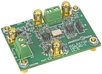
160160-1: bare PCB for Radio board
Component List
Resistors
Default: 1%, 100mW, 0603
R1,R2,R10 = 1kOhm
R3,R5 = 56Ohm
R4,R6 = 120Ohm
R7 = 5.6kOhm
R8 = 22kOhm
R9 = 330Ohm, 1%, 250mW, 1206
Capacitors
Default: 0603
C1,C4 = 150pF
C2,C3 = 270pF
C5,C6,C8,C9,C11,C13-C18 = 100nF
C7 = 1nF
C10 = 8.2pF, ±0.25pF
C12 = 10pF
Inductors
L1,L2,L3 = 330nH, 5%, 310mA, fres 60 MHz (36502AR33JTDG, TE Connectivity)
L4,L5,L6 = 1000Ohm @ 100MHz, 200mA (HZ0603B102R-10, Laird Technologies)
Semiconductors
D1 = BAS70-04
LED1 = green, 0805
T1 = BFR520
IC1,IC2 = SA602AD, SO-8
Miscellaneous
K1,K2,K3,K5 = SMA connector, straight jack, 50Ohm
K4 = 3-pin pinheader, 0.1” pitch, vertical
K6,K7 = 2-way PCB screw terminal block, 0.2” pitch
FL1 = 45MHz crystal filter, 1kOhm, BW=15kHz (see text), e.g. Golledge crystal filter GSF-75 45R15B1 45.0MHz
PCB # 160160-1
Discussion (0 comments)