Article
Volume Control for RPi Audio DAC
loud and quiet in high quality
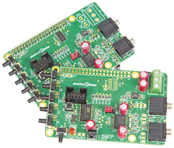
To the delight of many, the previous issue of Elektor had a high-quality network audio player based on the Raspberry Pi/Volumio combination, which however was not provided with a 'real' volume control. Although it is possible to control the volume via Volumio (what’s in a name), but this method seriously affects the high-end characteristics of the DAC for the worse. That is why we now describe a volume control especially developed for the network audio player.
Gerber file
CAM/CAD data for the PCB referred to in this article is available as a Gerber file. Elektor GREEN and GOLD members can exclusively download these files for free as part of their membership. Gerber files allow a PCB to be produced on an appropriate device available locally, or through an online PCB manufacturing service.
Elektor recommends the Elektor PCB Service service from its business partner Eurocircuits or AISLER as the best services for its own prototypes and volume production.
The use of our Gerber files is provided under a modified Creative Commons license. Creative Commons offers authors, scientists, educators and other creatives the freedom to handle their copyright in a more free way without losing their ownership.
PCB
Extra info / Update
* High-end volume control
* Suitable for Raspberry Pi + audio DAC
* Compact sandwich construction
* Uses an RC5 remote control
* Also suitable as stand-alone volume control
* Suitable for Raspberry Pi + audio DAC
* Compact sandwich construction
* Uses an RC5 remote control
* Also suitable as stand-alone volume control
Component list
From the Store
160321-1 Bare printed circuit board
160321-91 Assembled module (headers supplied separately — DIY soldering)
160198-91 Assembled Audio DAC module (headers supplied separately — DIY soldering)
SKU 17631 Raspberry Pi 3 (model B
Component List
Resistors
R1,R2,R3,R4,R5,R6,R7,R8,R11 = 47Ohm, 125mW, 1%, SMD 0805
R9,R10 = 2.2kOhm, 100mW, 5%, SMD 0805
R12 = 10kOhm, 100mW, 5%, SMD 0805
R13,R14,R15,R16,R17,R18 = 470Ohm, 100mW, 5%, SMD 0805
Capacitors
C1,C2 = 22pF, 50V, 5%, C0G/NP0, SMD 0805
C3,C4,C5,C13,C14,C17,C18 = 100nF, 50V, 10%, X7R, SMD 0805
C6,C8 = 100nF, 25V, 5%, C0G/NP0, SMD 1206
C7,C9,C10,C15,C16 = 10µF, 35 V, 0.04Ohm, 6.3mm max. diam., pitch 2mm or 2.5mm, Würth Elektronik 870055673001 (WCAP-PTHR Series)
C11,C12 = 4.7µF 25V, 20%, X5R, SMD 0805
Inductors
L1,L2,L3,L4,L5,L7 = 600Ohm @ 100MHz, 0.15Ohm, 1.3A, SMD 0603, Murata BLM18KG601SN1D
L6 = ACM4520-231-2P-T (TDK), 2 x 0.05Ohm, 230Ohm @ 100MHz, 2.6 A, SMD
Semoconductors
LED1 = red, T-1, 3mm
LED2 = green, low-power, SMD 0805
IC1 = ATtiny861A-SU, SOIC-20, programmed with firmware # 160321-11 (or 160321-12)
IC2 = PGA2311UA, SOIC-16
IC3 = TSOP34436, 3-pin epoxy package
IC4 = M74VHC14DG, SMD SOIC-14 (ON Semiconductor only)
Miscellaneous
K1 = 40-way (2x20) GPIO stacking socket (female), extra long
K2,K3,K7 = 3-way bus strip, vertical, 0.1’’ pitch (mounted on the bottom side of the board), with long stack-through pins
K4,K5 = 3-way stereo jack, 3.5mm, PCB mount, e.g. Lumberg KLBR 4
K6 = 6-way (2x3) boxheader, vertical, 0.1’’ pitch
K8 = 3-way PCB screw terminal block, 0.2’’ pitch, 630V
JP1 = 3-pin pinheader, vertical, 0.1’’ pitch
LED1 = 2-pin pinheader, vertical, 0.1’’ pitch
JP1 = jumper, 0.1’’ pitch
S1,S2,S3,S4,S5,S6 = pushbutton, right angle, SPST, FSMRA4JH TE Connectivity
S7 = pushbutton, SPST, FSM4JRT TE Connectivity
X1 = 12MHz miniature quartz crystal, 5x3.2mm, SMD, Cload 18pF
4 pcs 17mm M2.5 spacer (05.12.173 Ettinger)
4 pcs 6mm M2.5 bolt
4 pcs M2.5 nut
PCB 160321-1 v1.1
Optional
To support the LC display (instead of 4 bolts): 4 pcs 14mm M2.5 spacer (Ettinger 05.12.143)
Discussion (0 comments)