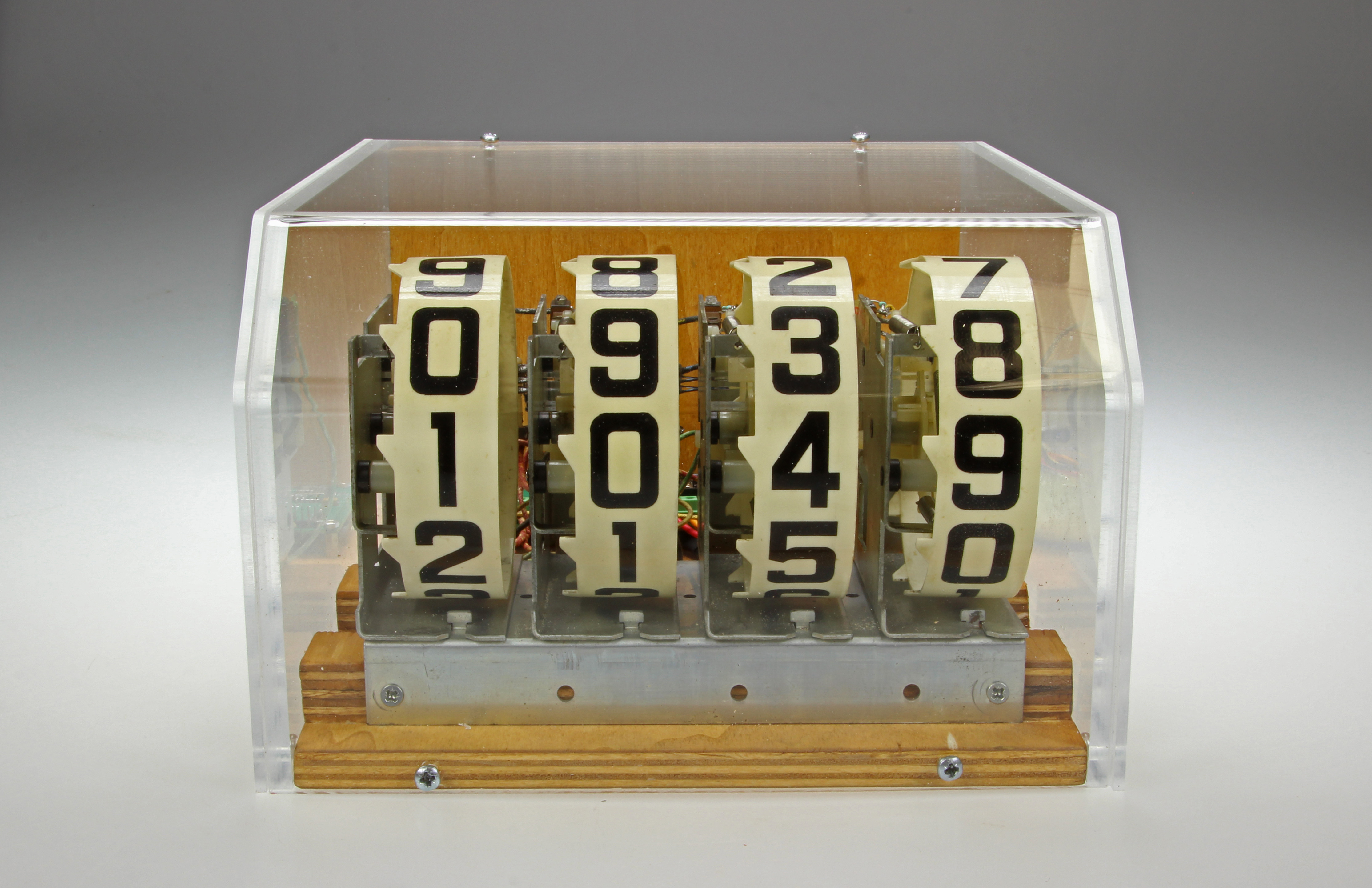
Beat the Elektor Pinball Clock!
Ah… the sound of them score drums rolling …

Materials
Gerber file
CAM/CAD data for the PCB referred to in this article is available as a Gerber file. Elektor GREEN and GOLD members can exclusively download these files for free as part of their membership. Gerber files allow a PCB to be produced on an appropriate device available locally, or through an online PCB manufacturing service.
Elektor recommends the Elektor PCB Service service from its business partner Eurocircuits or AISLER as the best services for its own prototypes and volume production.
The use of our Gerber files is provided under a modified Creative Commons license. Creative Commons offers authors, scientists, educators and other creatives the freedom to handle their copyright in a more free way without losing their ownership.
Components
The BOM (Bill of Materials) is the technically exhaustive listing of parts and other hardware items used to produce the working and tested prototype of any Elektor Labs project. The BOM file contains deeper information than the Component List published for the same project in Elektor Magazine. If required the BOM gets updated directly by our lab engineers. As a reader, you can download the list here.
Want to learn more about our BOM list? Read the BOM list article for extra information.
Component list
Component List
Resistors
R1,R2,R8,R9,R11,R23,R26 = 10kΩ, thick film, 5%, 0.1W, 150V
R3,R6,R10,R12,R19,R21,R24 = 100Ω, thick film, 5%, 0.1W, 150V
R4 = 2.7kΩ, thick film, 5%, 0.1W, 150V
R5 = 1k6Ω, thick film, 1%, 0.1W, 150V
R7,R15,R16,R17,R18,R20,R22,R25,R27 = 1kΩ, thick film, 5%, 0.1W, 150V
R13,R14 = 4.7kΩ, thick film, 5%, 0.1W, 150V
Capacitors
C1 = 4700µF, 50V, 10mm pitch, 22x41mm
C2,C6,C7,C8 = 100nF, 50V, X7R, 0805
C3,C4 = 100µF, 16V, 2312
C5 = 10µF, 16V, 1206
Inductor
L1 = 470µH power Inductor (SMD), 570mA, shielded, 270mA, MSS7341T series
Semiconductors
D1,D2,D3,D4 = S3J+, 600V, 3A
D5 = MBRS540, 40V, 5A, Vf=550mV @ If=5A
LED1 = green, 3mm
LED2 = red, 3mm
T1,T2,T3,T4,T5,T6,T7 = NTF3055L108T1G MOSFET, n-channel, 3A, 60V, 120mΩ
IC1 = LM2576HVS-ADJ, step-down regulator, 4-60V, 3A
IC2 = DS3231MZ+ RTC, I2C, 5ppm
IC3 = MCP23008-E/SO, 8-bit I2C I/O expander
MOD1 = ESP-12F, ESP8266-based Wi-Fi module
Miscellaneous and/or not on PCB
Bt1 = CR2032 battery, with holder, e.g. Keystone 1066
D6,D7,D8,D9,D10,D11,D12 = 1N4007, 1000V, 1A (not on PCB!)
F1 = 2AT fuse, 5x20mm, with holder, PCB mount, pitch 22.6mm
F2 = 160mAT fuse, 5x20 mm (230V mains) with holder, panel mount, solder terminals
F2 = 320mAT fuse, 5x20 mm (115V mains) with holder, panel mount, solder terminals
K1 = 6-pin pinheader, 0.1" pitch, vertical
K2 = 5-way PCB screw terminal block, 0.2" pitch, 630V
K3,K4 = 2-way PCB screw terminal block, 0.2" pitch, 630V
K5 = 4-way PCB screw terminal block, 0.2" pitch, 630V
K6 = 4-pin pinheader, 0.1" pitch, vertical
LCD1 = 0.96" Inch 128x64 OLED LCD Display for Arduino (optional)
R28,R29,R30,R31 = 1.2 kΩ, carbon film, 5%, 0.25W, 250V (not on PCB!)
S1 = switch, tactile feedback, e.g. SKHHLVA010
S2 = switch, tactile feedback, 12V, 50mA, Multicomp TM series
Tr1 = transformer, toroidal, 2x12V, 30VA, e.g. Multicomp MCTA030/12
Power entry connector, IEC320 C8 + cable
PCB 180307-1 V3.1


Discussion (0 comments)