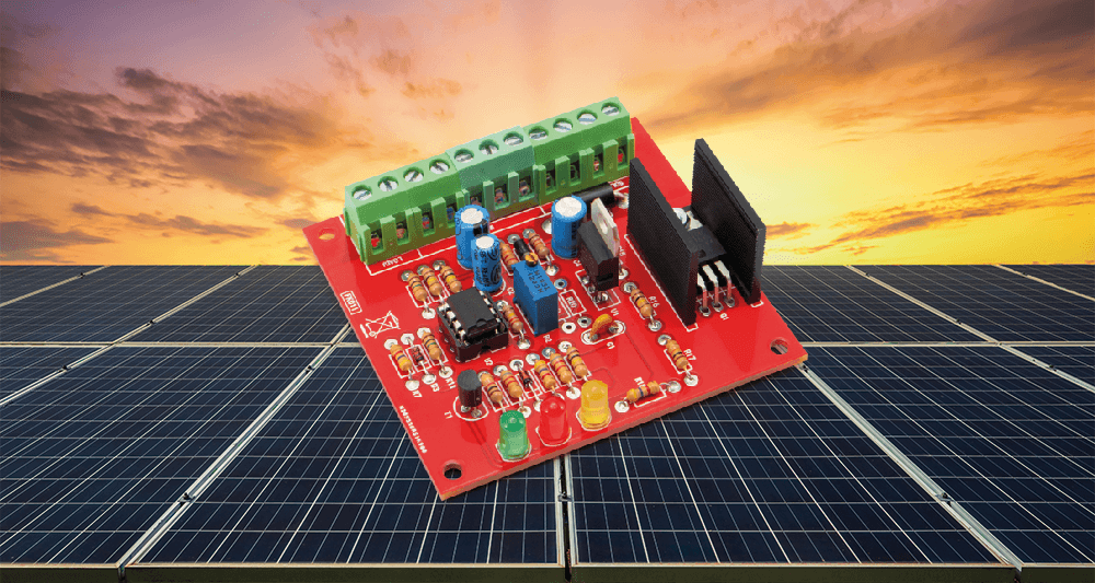
Simple PV Power Regulator
Build Your First, Fully Functional PV Energy Management System
This is a MEMBER ONLY article. You need a subscription to read this article.
- Access to Elektor archive and 5,000+ Gerber files
- Receive up to 8 magazines per year (digital and/or paper)
- 10% discount in the Elektor store
Available from €4.95 per month.
What is Members Only
Elektor is committed to providing high-quality content on electronics, catering to tens of thousands of paying members. As part of this commitment, Elektor has launched Premium, an initiative that offers exclusive online articles to members sometimes even before they appear in the magazine.
Every day, members can access in-depth articles that showcase the best of Elektor's premium content.
This initiative aims to reward members with early access. Once logged in, members can easily enjoy this exclusive content and engage in discussions about featured projects. While Premium adds to the existing resources available, Elektor will continue to provide a wealth of free information.
Join the Elektor community today to take advantage of Premium and other benefits!
Materials
Component list
Component List
Resistors
R1 = 22 kΩ
R2 = 10 kΩ multiturn trimmer
R3 = 12 kΩ
R4 = 330 kΩ
R5, R12, R13, R16 = 100 kΩ
R6, R7, R18 = 4,7 kΩ
R8, R9 = 8,2 kΩ
R10 = 1 kΩ
R11, R14 = 1 MΩ
R15 = 220 kΩ
R17 = 10 kΩ
R19, R20 = See text.
Capacitors
C1 = 100 nF, ceramic
C2 = 1 µF, 63 V, electrolytic
C3 = 22 µF, 25 V, electrolytic
C4 = 47 µF, 25 V, electrolytic
Semiconductors
D1 = 1N4007
D2, D3 = 1N4148
D4 = 1N5408
LD1 = LED, yellow, 5 mm
LD2 = LED, green, 5 mm
LD3 = LED, red, 5 mm
U1 = 7805
U2 = LM358
T1 = BC557
Q1 = IRF540
Miscellaneous
4+4 Pin DIL IC Socket
ML26 Heath Sink
1x 3MA x 10 mm Screw
1x 3MA Nut
4x Screw Terminal Block, 2 poles, 5 mm pitch
1x Screw Terminal Block, 3 poles, 5 mm pitch
PCB Board (69x72 mm)
Discussion (0 comments)
Rol 1 year ago
It explicitly says: “.... Figure 1, not only regulates the battery charge, holding it when it reaches its limit voltage, but also manages the load, connecting the battery when its voltage is high enough to keep the downstream load running, and disconnecting when the voltage becomes too low”. I can't find any component in the circuit that can do this!??However, this function would be very important in order not to destroy the battery due to deep discharge. The current consumption of the regulator alone could lead to this in winter without sunlight.
I find the explanation of the current regulation, in which Q1 absorbs the current, very confusing. It makes you think of a shunt regulator as described in the solar regulator article in elektor 3/2000.
DE183712 8 months ago
gibt es da irgendwo eine Richtigstellung zw. eine Ergänzung?
Lg Huber Elmar