

8-Bit Companion for the Raspberry Pi: Power Saving Simplified
on

Raspberry Pis and other single-board computers (SBCs) are ideal for sophisticated process control, but require significantly more power than microcontrollers (MCUs). Why not combine the best of both worlds? Here we show you how to get an 8-bit PIC to switch on a Raspberry Pi whenever it is needed.
SBCs with Unix capability facilitate the development of complex control systems. Especially in scenarios with high demands on GUI and data processing, they are superior to MCUs. Unfortunately, power consumption and real-time capability leave some room for improvement. Why not harness the advantages of both? If you want to trim an off-the-shelf single-board computer to exhibit lower power consumption, you can achieve this with a companion microcontroller. As an example, we want to implement a system that adheres to programmed downtimes and carries out an “alarm start” in response to a specific external event.
The Circuit Concept
In principle, the circuit works as shown in the flowchart (Figure 1). The voltage regulator acting as the main supply for the process computer (usually a switching regulator) is controlled by the microcontroller via its Enable input (EN).
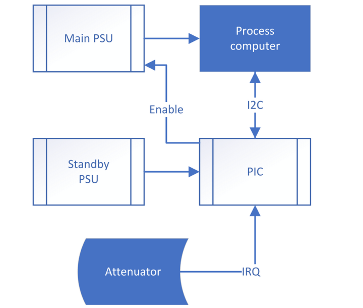
The MCU obviously requires a separate power supply that is independent of the EN input; due to the low energy requirement, a linear regulator is the most economical solution here. In general, the concept is completely component-agnostic; the author likes to use modern PIC16F derivatives from Microchip.
Figure 2 shows the sub-circuit that informs the PIC when the SBC (OPI = Orange Pi) is supplied by the external switching regulator (EXT). D1a, R9 and D7a implement a more or less “classic” attenuator, which breaks down input voltages in the range of up to 20 V to a value that is “manageable” for the inputs of process computer and microcontroller.

Splitting the series resistor into the values R7 and R9 is necessary because single board computers sometimes become a low-impedance load or have a residual voltage when they are switched off — without the resistor, this would cause the power management microcontroller (connected via the PIC terminal) to see strange or invalid values.
R7 is an additional protective element — the inputs of the process computer are connected to the supply voltage and ground via protective diodes. When very high voltage levels occur, R7 ensures that the current flowing into these diodes is limited and the process computer is not damaged — C13 and R8 provide a small additional debouncing function.
It should be noted that the circuit shown here with its EXT input was connected “directly” to the vehicle electrical system in various school buses. As there are now several thousands of such systems on the market without failures, it has been proven to work.
The role of diode D1a as reverse polarity protection is also helpful — please believe the author, who also works in the logistics sector, that connecting batteries the wrong way round is one of the classic “sports” of a mechanic.
The Software Is the Key
Communication via I2C is generally unproblematic (but don’t forget the necessary pull-ups). The “secret” of this system lies in the software. The PIC implements a kind of state machine that is based on the states shown in Figure 3.

The implementation of the shutdown process is of particular importance. Unixoid operating systems tend not to react very kindly to rough shutdowns. A convenient and practical way to solve the problem is to implement a countdown timer: The SBC activates this countdown and then starts the shutdown of the operating system. After the (generously dimensioned) period of time has elapsed, the process computer is “inertialized” and can be disconnected from the power supply.
Of course, the PIC can also perform other tasks. In addition to storing serial numbers and other information (in order to make it harder to manipulate), it is also possible, for example, to perform basic control tasks on the PIC. Of course, more complex implementations are also possible: A complex MSR task, for example, would make a 32-bit MCU appear reasonable as the secondary controller.
Practical Experience
Trackers based on the circuit concept shown here are now being used in tens of thousands by one of the author’s customers, demonstrating the practical value of the design. Instead of a stand-by power consumption of around 200 mA, the system now gets by with just a few milliamperes. The author’s AN4121, published by Microchip, is available here and provides further information on the topic.
Editor's Note: This article (240210-01) appears in the bonus edition of Jan/Feb 2025
Questions or Comments?
Do you have questions or comments about this article? Email the author at tamhan@tamoggemon.com or contact Elektor at editor@elektor.com.


Discussion (0 comments)