Build an NTC-Based Analog Thermostat
on

If you want a solution to precisely control a device by temperature, check out this thermistor-based analog thermostat. With an adjustment range of approximately 0°C to 60°C, you can put it to use in aquariums, boilers and more.
With this simple and small-sized analog design, it is possible to drive any kind of external loads through an insulated set of NO-NC contacts (Normally Open, Normally Closed) of a relay, thus allowing you to control heating devices through the NC connection, or — with reverse logic — to regulate cooling with fans or air conditioning systems through the NO connection.
Analog Thermostat Circuit Diagram
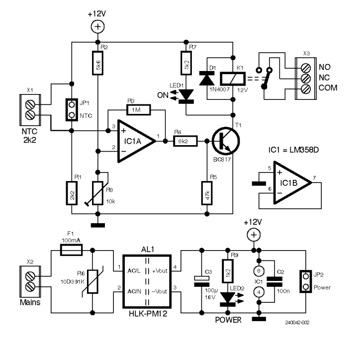
The thermostat circuit shown in Figure 1 consists of the operational amplifier IC1, used as a comparator, to sense the voltage difference between pin 3 (non-inverting input) referred to the NTC sensor applied to terminal block X1, and pin 2 (inverting input) fed by a voltage divider consisting of R2 and R8. Trimmer R8 allows the reference voltage at pin 2, i.e., the thermostat trip temperature, to be varied.
Negative Temperature Coefficient (NTC) thermistors have the characteristic of decreasing their resistance as temperature increases. They are widely used, over a temperature range of -100°C to 450°C, and valued for their high sensitivity and short response time. Their transfer curve has exponential trends that can be pseudo-linearized by connecting a bias resistor in series — as was done in this project — and eventually refined with resistor values placed in parallel to the NTC.

In this design, an NTC thermistor was used that has a nominal value of 2.2 kΩ at 25°C. To obtain a pseudo-linear response, the NTC was connected in series with R1 resistor, forming a voltage divider. In practice, when the NTC sensor is subjected to a temperature above 25°C, its internal resistance drops, causing the voltage at pin 3 to rise.
When the voltage at pin 3 exceeds the voltage present at pin 2, the output at pin 1 of the op-amp switches to logic level 1, causing T1 transistor to saturate and K1 relay to energize. If it proves difficult to find an NTC of the value of 2.2 kΩ, a component of the nearest value (at 25°C) can be adopted and resistor R1 replaced with one of identical value.
Trimmer R8 allows the switching threshold of IC1 to be adjusted. Resistor R3, connected between pin 3 and pin 1 of IC1, determines the hysteresis, which is the tolerance range (Δt) around the switching point. Without hysteresis, when the sensor temperature is close to the switching temperature — but does not permanently fall above or below that value — relay K1 could switch continuously, causing contact wear and possible malfunction of the controlled device. The presence of R3 ensures that the transition between the resting and active states occurs only when the temperature exceeds the switching threshold by a small margin, avoiding uncertainty at the time of switching.
Op-amp IC1B, which is not used, has been configured as an idling voltage follower, with non-inverting input on pin 5 connected to ground. This choice avoids noise and ensures proper operation of the circuit. The power for the circuit is supplied by PCB power supply module AL1, but it can also be drawn from an external source without installing this component on the PCB.

PCB
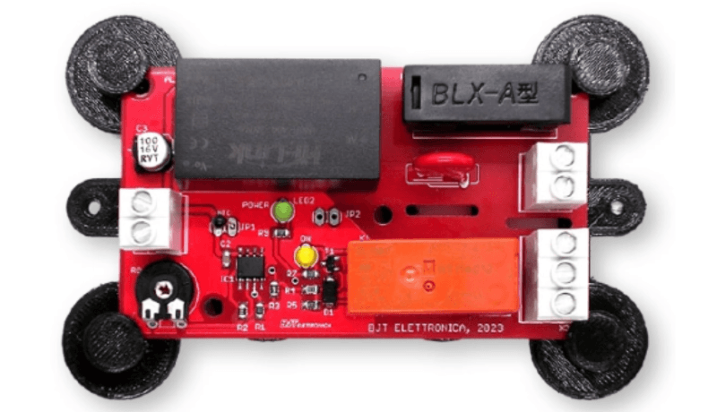
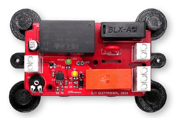
As can be seen from the finished prototype shown in Figure 2, mounted on 3D-printed supports, the circuit was made largely from SMD components, with the remainder using through hole mounted elements. The construction of the board is simple, although SMD components require more care in placement and soldering.
The board used is double-sided with plated-through holes, and it should be populated by following the silkscreen shown in Figure 3. If the thermostat is used to control the AC line voltage, the millings shown in black in the same picture must also be made, to increase the isolation between the mains voltage and the low-voltage section of the circuit.
Circuit assembly requires some specific tools for placing SMD components, as well as a certain amount of manual dexterity. The soldering iron should preferably be a very fine-tipped type and with a power rating of no more than 12 W. The use of an SMD soldering station is still the best choice. Tin wire should be no more than 0.5 mm thick. The layouts for the PCB, including the .stl file for the 3D-printable supports, are available for download below.

insulation between the mains voltage section and the low-voltage area of
the circuit are well visible.
Assembly and Testing
You can start by applying IC1 respecting its orientation and soldering one pin at a time, in alternating rows. Next, the resistors and ceramic capacitors can be treated. Finally, D1 diode, T1 transistor, C2 and C3 electrolytic capacitor can be placed.
Please note that due to a mistake in the deployment phase of the PCB, the component count for the capacitors started from 2; therefore, there’s no C1 on board. Don’t look for it!
At this point, one can move on to the assembly of the through-hole components. You have to insert LED1 and LED2 diodes, then X1, X2 and X3 screw terminals, F1 fuse holder, AL1 power supply, and finally R8 trimmer and R6 varistor.

COM-NO contacts are used to control a
heating device, while COM-NC may control a cooling system
Please note that the NTC leads can either be connected to JP1 pads or to X1 screw terminal block, whose contacts are connected in parallel through the PCB. Furthermore, one of the two could be utilized for connecting a compensating resistor in parallel to the NTC, in case a specific linearization curve was needed.
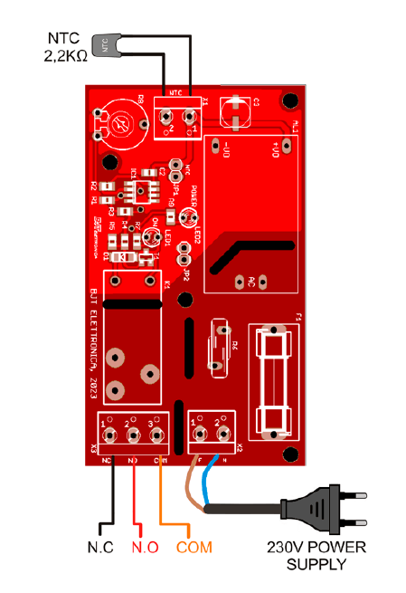
Once the assembly is finished, you can proceed with testing. Figure 4 shows the necessary wiring. If you connect high-current loads to the relay PCB tracks going to terminal X3, you need to thicken them with tin, as shown in the bottom-right corner of Figure 5.

visible in the bottom-right corner. This allows to
control heavier loads without heating the copper tracks.
For testing, you should set R8 trimmer to one-fourth of the travel (CW) and supply power to the board. The green LED2 should light up. By heating the NTC thermistor, LED1 will light up and at the same time you will hear K1 relay tripping. If everything has gone as described, the circuit is operational, ready to be adjusted to the desired trip temperature and used in your application.
Questions or Comments?
Do you have technical questions or comments about this analog thermostat design? Email the author at lrgeletronic@hotmail.com or contact Elektor at editor@elektor.com.
Editor's Note: The article (240042-01) appears in Elektor Circuit Special 2024, which hits newsstands in August 2024.


Discussion (11 comments)
Qynx 9 months ago
R1 to R8 must be R1 to pin 3 IC1a ?
best regards,
Rob Keij
EN0204139ID 9 months ago
Senior Editor, Elektor 9 months ago
Roberto Armani
Qynx 9 months ago
best regards,
Rob Keij
audeq2 9 months ago
Martin Fuhrer 9 months ago
F1Andy 9 months ago
The text says the NTC is linearized with 2k2 in series - this is not correct.
This just creates a potential divider of half supply voltage when the temperature is 25 degrees C.
To linearize as stated, you need a resistance in parallel with the sensor, (this is alluded to later in the text though). Linearization is not really required here as it is a single set-point, but you need to select an NTC that will have a sensible change in resistance near your desired operating point. 2k2@25 is suitable for refrigeration temperatures. 10k@25 or 22k@25 are better suited to room temperatures and domestic hot water.
The current through the sensor will have a self heating effect, so using a 2k2@25 sensor like this can give varying trip points as the sensor is warmed by the circuitry that controls it.
As mentioned by audeq2, you should use a comparator. The common mode voltage to the LM358 input is "(V+) -2V", and it is also subject to output phase reversal when common mode input voltage is exceeded. This will happen if the sensor is at above 70 degrees C or so. If you are going to use an op-amp as a comparator, then this is a bad choice of device.
If you were to stick with a dual op-amp, the free op-amp could be easily used a constant current supply to the NTC and eliminate the self heating issue mentioned above. This will allow use of a relatively long sensor cable too.
The input also has no filtering on it, so any noise picked up by the sensor wiring when near to the trip point can cause an early activation or deactivation.
PCB does not have any "Danger Live Parts" warnings, or earthing. Readers should not make this!
PAUL BROWN 9 months ago
Senior Editor, Elektor 9 months ago
Roberto Armani
Angel59 9 months ago
Senior Editor, Elektor 9 months ago
thanks for bringing this issue to our attention.
We fixed it, refresh your browser and try again.
Roberto Armani