

Build Your Own Four-Axis Multifunctional Z99 CNC Machine
December 26, 2022
on
on
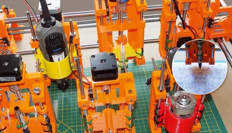
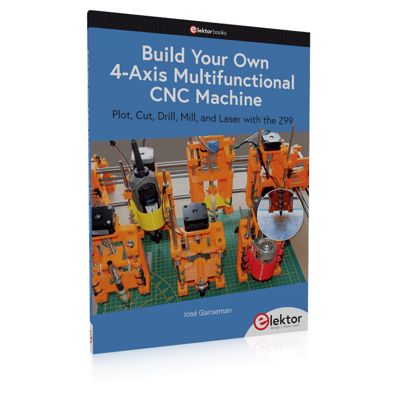
My book, Build Your Own 4-Axis Multifunctional CNC Machine (Elektor 2022), is about the construction, hardware, software, and operation of the Z99 CNC machine. Finally, we dare to say that anyone who can drill a hole in a Medium Density Fiber (MDF) baseplate can construct the Z99.
Why the Name “Z99”?
Z99 can be defined as a multifunctional four-axis machine for home construction. All the options use the same XY mechanism. The only component with some differences is the Z carriage. Previous names we thought of were Z3, Z4, Z5... However, the number of possibilities is not yet exhausted, hence the name Z99. Perhaps the number 99 is also close to the number of prototypes we have built.What's more, Z99 is a DIY device. It allows the user to plot, cut, drill, laser and mill, and the construction and use are simple. Most of the parts come from the world of 3D printers.
The Capabilities of the Z99 Machine
Curious about the machine's features and its uses?- large-format schematic plotting
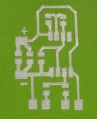
- PCB plotting with etch-resist pens
- schematic plotting with conductive-ink pens
- letter cutting out of vinyl
- paper cutting
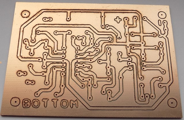
- PCB/substrate drilling
- PCB/substrate milling
- text milling
- laser engraving
- laser cutting of solder paste masks
Software
By making the support software available as freeware, readers of the book are challenged and encouraged to develop new applications for the Z99. The download contains all the 3D files, the complete C# source code, the microcontroller code, the PCB layout and the schematic design and the Windows software XYZ.exe. Examples files are in the download.Equally important, the machine would not be of much use if the user has no option to create suitable files for the designs in mind. A large part of this book is dedicated to creating source files in a variety of freeware software packages, including Inkscape, DesignSpark PCB, KiCad and FlatCAM.
The New Elektor Book
The book, Build Your Own Multifunctional 4 Axis Machine, is also useful for readers keen to comprehend and then master the basic structure of HPGL, Gerber, Drill, and G-code files, as well as to have a go at deciphering them using software. In addition, there is a chapter in the book on how to successfully print large 3D parts. With the aid of the Elektor book and some patience, you will succeed in building a reliable Z99. Nevertheless, do not try to build and use all 'Z' possibilities at once. And don't forget that new software takes some time to master and that learning is a lifelong hobby. This is even more the case when that software is tightly coupled to the hardware.With materials available as freeware for the readers of the book, we hope that new applications will be developed. Lastly, we hope that you will experience as much joy building and using the Z99 as we had in developing it!

About the Author
Dr. José Ganseman (1951) was occupied as general practitioner for 35 years.
Read full article
Hide full article
Discussion (6 comments)
David Reid 2 years ago
David
peterc 2 years ago
KenArton 1 year ago
Is there a kit of parts available, or alternatively a list of parts, so that I can get an estimate of cost before I go ahead and buy the book ?
Thanks, Ken.
J.F. Simon, Elektor 1 year ago
Content Director, Elektor 1 year ago
"https://github.com/opaJG/Z99
The electronic parts are visible in the preview of the book on the Elektor site. A summary of the mechanical parts is in the book on page 53."
K. Horton 1 year ago
I am about to start ordering parts to build a Z99 and wondered if there were any upgrades or enhancements that I should know about?
I have read through the book quickly and and now reading it in more detail.
I have noticed that there are a lot of discrepancies between the KiCad schematic and the actual PCB layout. Most concerning is that D2 and D3 are both shown the wrong way round in the schematic and both are effectively short circuits! Also many of the capacitor and resistor numbers do not correspond with the silk screen overlay.
Is it possible to have a copy of the DesignSpark PCB schematic file as I use this for all my work and as it was the original file for the PCB, presumably it does not have the inconsistencies that have crept in to the redrawn KiCad schematic. Unfortunately, this file is not included in the ZIP file.
Also, I think page 29 should read 0.600 V (or 600 mV).
Regards
Ken