The 4000-series of CMOS logic devices has over 150 members. Let's take a look at the curious case of the CD4060.
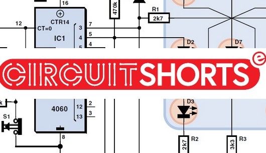
The 4000-series of CMOS logic devices has over 150 members. The first one was introduced in 1968, but remarkably, many of them are still available and in production today. When I wanted to design a digital die, I spent a few days designing my own until I ran into an Elektor project called "Dicing with LEDs." I was charmed by how creative it was and saw no reason to even try to improve on it. It uses the CD4060, a 16-pin package "14-stage binary ripple carry counter/divider with oscillator."
A clever circuit.
A counter is made up of a chain of flip-flops (which flavour of flip-flop depends on the type of counter and implementation choices). A "ripple" counter is asynchronous which means that its flip-flops are not clocked from a common clock, but the update of state ripples through the chain, triggered by an input signal. (That input signal may look like a clock, but it’s just a signal.) The 4060 is a binary "counter," but its common use is to "divide" the input trigger by powers of two at each of the counter stages. The highlight of the 4060 is that it has a built-in oscillator, so we don’t need an extra chip to generate the trigger for a "free running" counter!
The “Dicing with LEDs” is a really clever circuit, and I encourage you to look at it to see how the CD4060 can be used creatively. But what’s the curious case?
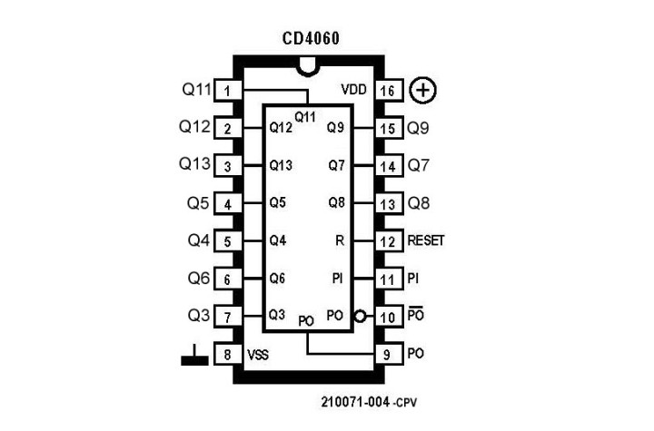
Q0, Q1, Q2, and Q10 are missing from the pinout.
If you look closely at the pinout, you’ll notice that it’s missing some outputs: Q0-Q2 and Q10 (interestingly, some 4060 variant pinouts start at Q1, like TI's CD4060 while others like TI's SN74HC4060 use QD-QJ, QL-QN). The prevailing large package at the time had 16 pins so you couldn’t have it all: 14 (counter) + 3 (oscillator) + 2 (power) + 1 (reset) = 20 pins. Omitting the least significant bits of the counter is understandable since dividing by up to eight can be done simply in various other ways. But why Q10 that divides the trigger by 2048?
I don’t have an answer, but my guess is that the designers thought that it’s available in the 4020 (also a 14-stage ripple counter) so there’s an option if someone really needed that output. But it looks rather arbitrary to me. Why not omit Q8? Do you know?
Additional Resources About CD4060, Electronic Dice, and More
Interested in circuit design, CMOS, CD4060, and related topics?


Discussion (4 comments)