
A DC-DC Power Converter to Upgrade Fixed-Voltage Sources
on
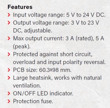
DC-DC converters can be very useful on your workbench. These circuits can generate different regulated voltage outputs, from the input voltage supplied by a battery or a fixed-voltage power supply. This DC-DC power converter design can transform a 5-to-24 V DC input voltage into different, regulated output voltages that can be selected by adjusting a trimmer.
DC-DC Power Converter Design
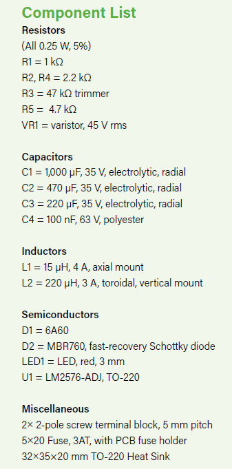
As you can see in Figure 1, the schematic is straightforward. F1 and VR1 protect against input voltage spikes. D1 prevents damage to the IC in case the circuit is accidentally powered with reversed polarity. C2 is the input filter capacitor. R1 is the bias resistor for LED1 that indicates the power-on status of the converter.
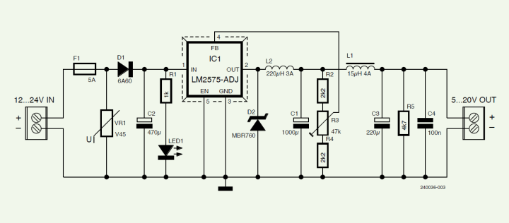
At the core of the project is IC1, an LM2576-ADJ switching voltage regulator by Texas Instruments, configured as a step-down converter. It switches at the nominal frequency of 52 kHz and accepts a wide range of input voltages, from 5 V to 35 V. To regulate the output voltage, being a fixed-frequency type switch, this chip varies the on/off ratio (duty-cycle) of the signal that drives the series switching transistor, whose output is sensed — after the L-C smoothening filter made by L2 and C1 — through pin 4 (FB). This feedback input gets the signal from the adjustable voltage dividing network R2…R4, in which by adjusting R3 you can set the output voltage.
D2 has a key role in this kind of circuit. It’s the flyback (aka catch, freewheel, snubber, or clamp) diode that shorts to GND the negative voltage peaks generated by L2 every time the series switch transistor opens. For this diode, a high-recovery speed, Schottky-type is required. Refrain from using rectifiers that can’t handle high frequencies for D2.
Downstream the main L-C filter, a secondary stage was provided through L1 and C3, to further reduce the output ripple. The stand-by resistor R5 grants a minimum load to the circuit in case of no-load at the output, whilst C4 is the classic HF bypass capacitor.
This design features an average conversion efficiency of 88%. That’s quite high in respect to any other type of linear regulator we might use. In addition, an oversized heatsink allows continuous operation without any problem of overheating, even without a fan.
Assembly
A PCB was designed for the project, it’s a single-sided type. The construction of the board is simple; the silkscreen and the solder side layouts can be downloaded here. As you will figure out from the drawing of the component side, the design uses only through-hole elements, which do not give any assembly problems.
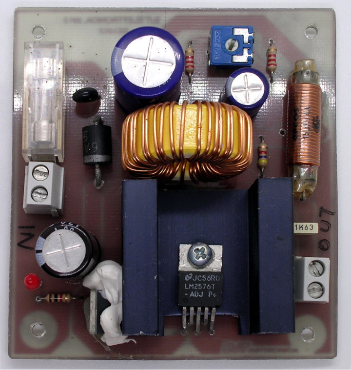
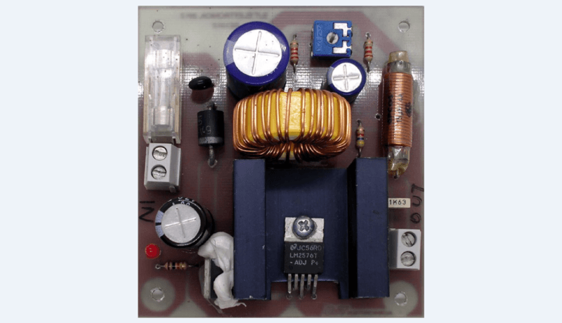
Simply follow the drawing, paying attention to the orientation of the polarized components. Assembling presents no difficulty, even for beginners. It will be enough to use a small-power soldering iron (30 to 40 W) with a fine tip and a solder wire no larger than 0.7 to 1 mm in diameter. At the end of the process, the converter will look like the prototype shown in Figure 2.
While switching converters offer a much higher efficiency than linear regulators, their high dynamics of operation require closer checking before final commissioning. It is advisable to connect a power resistor — rated for the power dissipated at the desired test voltage — to the output, checking with an oscilloscope the level of residual ripple and the absence of HF oscillations. At this stage, it is also possible to verify the maximum output voltage excursion, at a given input voltage, depending on our usage requirements.
Questions or Comments?
Do you have technical questions or comments about this article? You may write to the Elektor editorial team at editor@elektor.com.The original article, "DC-DC 3-A Power Converter" (240036-01), is slated to appear in the Elektor Circuit Special 2024, which will hit newsstands in August 2024.

Discussion (4 comments)