
ESP32-Based Energy Meter Project (Update 1)
on
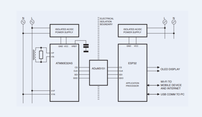
We began our journey of developing a reliable, user-friendly energy meter leveraging the ESP32 microcontroller. In our previous installment, “Prototyping an ESP32-Based Energy Meter," we discussed the initial design requirements, block diagram and the plan for starting this project. Before we give an update on it, let’s have a recap. The energy meter conceptual design is shown in the rendering in Figure 1.

Our focus was on real-time power monitoring, with an emphasis on safety and affordability. To make the energy measurement precise, we opted for the Atmel ATM90E32AS, a polyphase energy monitoring IC. This IC will get the single-phase voltage from the mains and will use split coil transformers to measure the current safely. The main application microcontroller selected was ESP32 as it has built-in Wi-Fi and very cost-effective when compared to other MCUs. In Figure 2, the project’s updated block is shown. The planned size of the final energy meter is 100×80×30 mm (L×W×H), but, for the prototype, our PCB is 100×100 mm. Our goal of this prototype is as proof-of-concept and, subsequently, if we’re successful in it, we’ll scale the size down to 100×80 mm or even less for the final version. The main purpose of making this energy meter was to make an IoT-enabled, budget-friendly device that can make accurate energy measurements and provide real-time energy data to the user via a mobile device, so the user can track their power consumption in real time and become more energy efficient.
In this article, we dive deeper into the project’s evolution, highlighting the schematic design, the implementation of circuit isolation, and the key improvements we’ve integrated since our initial concept.
Schematic Design
The heart of our project lies in its schematic design. The ESP32 microcontroller remains central to our architecture, interfacing seamlessly with the ATM90E32AS for energy measurement. Our updated schematic reflects a more streamlined approach, reducing noise and enhancing signal integrity, circuit isolation, and more. In Figure 3, you can see the complete schematic of the project.
IC1 is the ATM90E32AS which is the brain of this entire project, it connects the mains voltage with series seven 240 k resistors (R1…R7) to pins V1P, V2P, and V3P. For keeping things simple, all these pins will be given a single-phase voltage from the mains. You might ask, why not use a transformer instead of these series of resistors? Because as we have size and cost constraints due to the approach we chose. Apart the small size benefit of using resistors there is another benefit, that is less Phase Delay. Transformers can introduce a phase delay between the primary and secondary windings, which could affect the timing and accuracy of voltage readings in energy measurements. When using resistors, this phase delay is significantly reduced, potentially leading to more accurate real-time voltage readings. But, using these series resistors has a major disadvantage, i.e., no galvanic isolation. We will talk about this later in the article.

Now moving to the current measurement: For that we will be using coil transformers (CTs). Connectors K1-K3 are audio jack connectors where the SCT013 by YHDC will be connected, which is a split core type CT, shown in Figure 4. The reason for selecting CT was that it is cost-effective easy to use, and non-invasive.
The energy metered is powered by two Hi-Link HLK-5M05 modules ACDC1/2, to ensure galvanic isolation between the MCU and energy meter circuitry, protecting against high-voltage risks. AMS1117-3.3 regulators provide stable 3.3 V power, essential for the ESP32 and other low-voltage parts. Safety is further bolstered by fuses (F1) for overcurrent protection and a metal oxide varistor (MOV) (R23) against voltage spikes. For diagnostics, LED1 and LED2 indicate power and operational status. Connector K6 connects to all the outputs for the MCU for debugging operations.

Circuit Isolation
In the schematic, you might have noticed two DC grounds, GND and GNDA. The ground terminal (GND) is connected to IC1 and is also connected to the AC mains neutral. GNDA is an isolated ground terminal that is connected to the ESP32-WROOM-32D, which is MOD1. To ensure safety, it is imperative to isolate the ESP32 from the AC mains neutral. As the IC1 lacks galvanic isolation, it is imperative to isolate these components from each other. Now, the question arises as to how the SPI between these two chips will be communicated. Here is when IC2, an Analog Devices ADuM3151, comes into play.
The ADuM3151 is pivotal in ensuring safe communication between IC1 and the ESP32-WROOM-32D, providing galvanic isolation for SPI lines. In Figure 5, you can see the functional block diagram of IC2. It uses inductive couplers to transfer digital signals across an isolation barrier, effectively shielding the computer-connected ESP32 from the AC mains’ high-voltage transients. This choice is crucial for preventing damage during coding and debugging, while its capability of supporting multiple isolated channels ensures reliable and secure SPI communication, maintaining data integrity and aligning with the project’s safety and performance goals.

User Interface and Interaction
The user interface of the ESP32 Energy Meter project is designed to be informative and user-friendly. An OLED Display, connected to connector K5, which is interfacing with the I2C pins of the ESP32, will serve as the primary display medium. This display will show all relevant data to the user in real-time, including energy consumption metrics and system status. The choice of OLED technology ensures clear visibility and a responsive interface.
In addition to the hardware display, the project incorporates a web server hosted on the ESP32. This web interface will mirror the data displayed on the OLED screen, offering users an alternative way to monitor their energy usage. The development team is dedicated to creating a web UI and UX that is both user-friendly and detailed, ensuring accessibility and comprehensiveness in data presentation. This dual-interface approach allows users to interact with the energy meter both physically and remotely, enhancing the overall usability of the system.
ESP32-Based Energy Meter: Future Plans
As the project moves forward, the initial PCB design has been sent off for manufacture. Upon its return, the focus will shift to the firmware side of the project. The firmware development will involve programming the ESP32 to accurately process and display energy consumption data, manage the web server, and ensure smooth communication between all components.
Looking ahead, there are plans to integrate additional features to enhance the energy meter’s functionality. These may include:
- Remote monitoring capabilities: Allowing users to check their energy consumption data from anywhere via the web interface.
- Alerts and notifications: Implementing a system to alert users about unusual energy consumption patterns or potential system issues.
- Data analysis tools: Incorporating analytical tools in the web interface to help users understand their energy usage trends and identify areas for efficiency improvements.
We are committed to continuous improvement and innovation, with a focus on user feedback to guide future enhancements. The goal is to not only provide a reliable energy monitoring tool, but also to empower users with insights into their energy usage, fostering awareness and efficiency.
This article originally appeared in Elektor Jan/Feb 2024 (230709-01). Check out the ESP32-Based Energy Meter Series.


Discussion (0 comments)