
ESP32-Based Energy Meter Project (Update 2): Some Enhancements
on
In 2023, we started with the goal of creating a reliable, user-friendly energy meter using an ESP32 microcontroller. In our last article about the ESP32-Based Energy Meter Project, we went over the block diagram, the schematics, circuit isolation strategy, features, and project strategy. Let’s start with a small recap before we get into the next update.
The main idea revolved around developing a precise and efficient energy meter leveraging the capabilities of the Espressif ESP32 microcontroller and the ATM90E32AS IC for energy measurement. The project aimed to enhance user experience and reliability through meticulous schematic design and circuit isolation using the ADuM3151 to provide safe communication between ESP32 and the ATM90E32AS by Atmel (now Microchip). It emphasized safety and efficiency by incorporating noise reduction techniques, signal integrity enhancements, and protective mechanisms such as fuses and MOVs. With a focus on future-ready features, the plan included integrating remote monitoring and data analysis tools for improved energy management and efficiency insights.
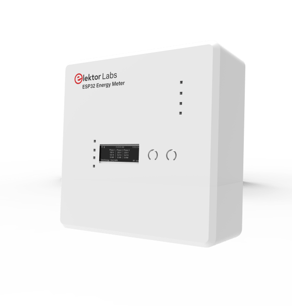
In this article, our main goals remain the same, and plenty of changes have been made to make the project safer to use, reduce its production cost, and reduce its size. As mentioned in the previous article, the size of the prototype PCB was 100×100 mm. After testing, some components were removed and the layout of the PCB was optimized, hence the size for this version is reduced to 79.5×79.5 mm — that’s about 20% less from last time. In Figure 1, the new enclosure for the new version of PCB is shown. Along with that, to make the ESP32 Energy Meter safer to use, instead of powering the PCB directly with the mains voltage, now a 220 V-to-12 V Step Down Transformer is required for voltage sampling and also powering the circuit. Adding a transformer does have some drawbacks in terms of phase delays, but safety first! Since we are not looking to measure voltage spikes, or fast sags or surges, but energy, this shouldn’t hurt our measurement.
The Updated Schematic Design
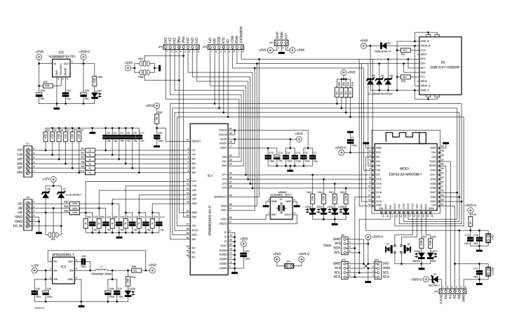
We made some upgrades, and now, rather than the ESP32, the ESP32-S3 is on board. This also unlocks more potential for the Energy Meter. The ESP32-S3 offers significant enhancements over the ESP32, including improved processing power, AI and signal processing capabilities, more memory, and better security features. The updated schematic further improves the capability of the Energy Meter along with more functionality. The design references guides from Espressif and other useful internet resources were used to integrate the ESP32-S3 into the project. In Figure 2, the schematic of the project is shown.
The circuit board layout has been optimized to improve the safety, usability, and efficacy of the ESP32-S3. We’ve made substantial adjustments by lowering the PCB size for a more compact footprint, moving to transformer-based power for increased safety, and adding versatility with single and three-phase compatibility. The utilization of a more efficient AP63203WU-7 buck converter in place of Hi-Link modules, along with the addition of user-friendly features such as a USB-C connector and a Qwiic connector for expandability, all contributed to the advancement of the project. These improvements build on the ESP32-S3’s capabilities, focusing on providing a practical, adaptable, and safer energy monitoring solution.
Refined Voltage and Current Sampling
IC1 remains the same ATM90E32AS, but the change is that it now requires a 220 VAC-to-12 VAC step-down transformer, between it and the mains. This change has been made to make the project more safe to test and use, as the transformers provide galvanic isolation. In my testing there was no notable difference in doing so.
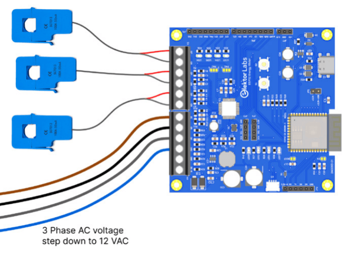
Thus, for each of IC1’s voltage sampling inputs, there is now only one 100 kΩ resistor (R27 to R29). Last time we combined all the phase voltages into one input, and a lot of feedback was given by the readers to have the option to use it with either three-phase or single-phase power if needed. We thought about it, and now we can use it with both. By default, three-phase mode is configured, but if one wants to make it single-phase, jumper JP8 needs to be shorted. Figure 3 shows the general wiring illustration for a three-phase system. Note that the phase wires are connected after the step-down to 12 VAC from a transformer — using a 12 VAC doorbell transformer can be useful in this case.
For current sampling and measurement, instead of using the headphone jack as the connector, a 5.08 mm pitch screw terminal block is used, i.e., K1. This adds to the overall ruggedness of the energy meter. For current coil sensors, the YHDC SCT013 100 A : 50 mA is selected and the resistors R1 to R12 for all three current sensing inputs are calibrated accordingly.
Energy Meter Project: Power Supply Optimization
The energy meter is now powered with buck switching regulator IC3, i.e., the AP63203WU-7 by Diodes Incorporated. Previously, Hi-Link HLK5M05 modules were used, but they are much bulkier and more expensive than this buck converter. This is done as buck converters are more efficient than these Hi-Link modules, they cost less, and their size is much smaller. Using IC3 also lets us power the circuit with 12 VDC at K4 for development purposes and also from the UA, i.e., voltage phase 1 of from the same connector, K4, for normal operation.
Interactive and Modular Features
For active, reactive, apparent, active fundamental, and harmonic energy pulse outputs CF1 to CF4, LEDs have been added. For the power mode selection of IC1, jumpers PM1 and PM2 are added. In this version, all the output pins of IC1 ATM90E32AS for MCU are provided on terminal JP5 and JP6. This enables the energy meter to be used as a module as well with another MCU if the onboard ESP32-S3 is not required.
The ESP32-S3 has the USB feature built in, so it’s really convenient to program the MCU this way, which is why we added USB-C connector K2. For troubleshooting, terminal JP2 has been added. Status LEDs LED1 and LED2, which can be controlled by the ESP32-S3, and push buttons S1 and S2 are added for interacting with the OLED screen, which can be connected to JP3 and JP4. Why two connection points? Some I2C OLED screens have ground as the first pin and some have 3V3 supply instead. This way, both types of OLED pinout variants can be worked with. Finally, the Qwiic connector at K3 has also been added to enhance the functionality of the Energy Meter, in case one wishes to add some additional sensors or modules to this project.
The PCB Layout
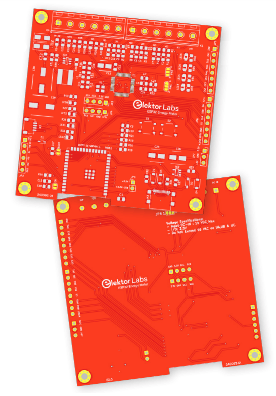
The PCB layout has been meticulously optimized for compactness, and easy soldering, shown in Figure 4. At the top, voltage and current sampling connections are strategically positioned in one place for DIN rail format integration. On the right side, connections for any external microcontroller (MCU) are facilitated through 2.54 mm pitch headers, ensuring ease of access and modularity. Centrally located is the connection for the OLED screen, flanked by push buttons for intuitive interaction. Adjacent to the OLED display, power and status LEDs provide immediate visual feedback, while energy pulse output LEDs are conveniently situated near the MCU output terminals for direct monitoring.
At the foundation of the design, the USB-C port and the ESP32-S3 module are positioned away from the AC voltage areas to improve safety. A ceramic capacitor, placed adjacent to the 3 V input of the ESP32-S3, serves to decouple and significantly reduce any potential noise. Additionally, electrolytic capacitors are incorporated into the design, further stabilizing the power supply and ensuring the circuit’s reliability and performance. This layout streamlines the assembly process and enhances functionality and user experience by providing a clear and logical component arrangement. In Figure 5, you can see the rendering of the assembled PCB.
Caution: This design requires the use of mains-powered transformers. People inexperienced with mains voltages should not attempt this project or should ask someone with experience who can help them with this project!
Meter Project: Next Steps and Prospects
Following the prototype phase with the original schematic, we’ve made several enhancements to increase the reliability of the ESP32 Energy Meter. Currently, we are also focusing on the further development of its firmware.
The latest PCB design has been dispatched for production, and we anticipate conducting extensive tests upon its receipt to ensure system reliability. Concurrently, software development is progressing, aimed at maximizing the capabilities of the ESP32-S3 module within our energy meter.
Looking forward, we plan to integrate the ESP32 Energy Meter with Home Assistant, aiming for simplified user engagement. Nevertheless, we are equally committed to developing bespoke firmware to fully utilize the device’s potential.
In summary, the project is moving forward with both hardware improvements and software advancements. Our goal remains to provide a dependable and efficient energy metering solution. This project is also on the Elektor Labs platform, so feel free to comment and contribute there!
This article, "Project Update #2: ESP32-Based Energy Meter Some Enhancements" (240093-01) first appeared in Elektor May/June 2024. Check out the ESP32-Based Energy Meter Series.


Discussion (0 comments)