
ESP32-Based Energy Meter Project (Update 3): Integration and Testing with Home Assistant
on
In our previous article, we focused on enhancements to the schematic design and PCB of the ESP32 Energy Meter, with improvements in modularity and safety features. Before we get into the next project update, let’s have a brief overview.
In the most recent advancements of the ESP32 Energy Meter project, we upgraded to the ESP32-S3 microcontroller, introducing enhanced processing power and broader functionality. The new design slimmed down the PCB and incorporated a transformer-based power system, using a 230-V-to-12-V Step Down Transformer for voltage sampling and running of the system. This significantly improves safety while maintaining flexibility for both single- and three-phase installations.
Other improvements included the integration of a more efficient AP63203WU-7 buck converter, making the PCB more modular, calibration of the current transformer sampling circuit, and more. This not only optimizes the energy meter’s performance and functionality, but also reduces both cost and size.
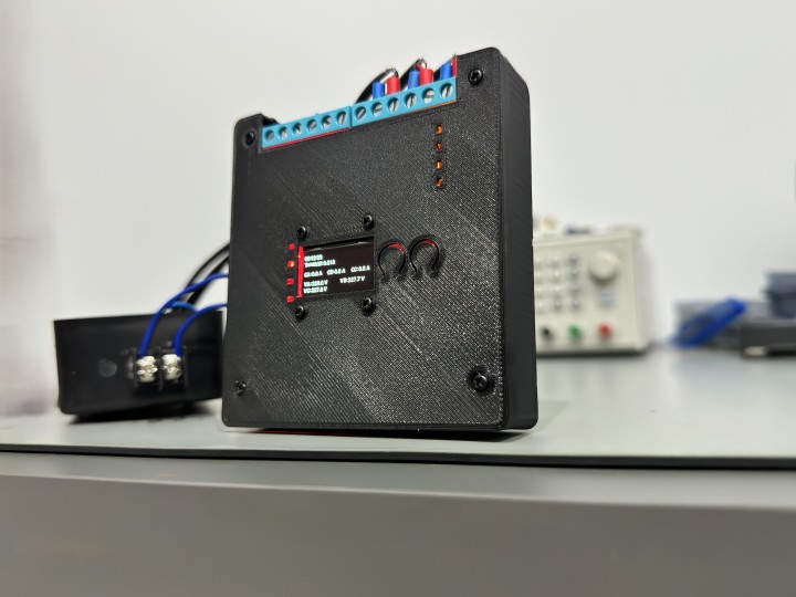
In this article, we will discuss the steps taken to get this energy meter up and running and the journey it took from the lab bench to the circuit breaker box. Furthermore, we will also discuss how to set it up, calibrate it, and finally, how to integrate it with Home Assistant with ESPHome to show and monitor the collected data from the energy meter. In Figure 1, a vivid snapshot of the ESP32 Energy Meter project in action is captured, encased in a 3D-printed enclosure with an OLED display. The image highlights live status indicators that seamlessly track and display real-time power consumption.
Energy Meter Assembly
The new PCB was designed to be more compact and straightforward to solder and the layout had adequate spacing for each component which accommodated the soldering process of it. To facilitate project replication and modifications by enthusiasts and professionals alike, the complete Bill of Materials (BOM) in Mouser format, and the production files are shared on the Elektor’s Lab GitHub repository.
For the voltage and current sampling connections, screw type terminal blocks by CUI Devices were used, the quality of these terminal blocks were much better than the cheap blue colored terminal blocks seen on most sensor modules. As we are dealing with AC Voltages and energy metering, it is vital to have secure and reliable connections.
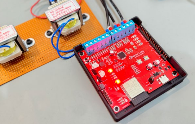
Noise reduction is a critical aspect of the PCB design, addressed by integrating both electrolytic and ceramic capacitors around the ATM90E32S energy metering chip. This arrangement helps to filter out both low- and high-frequency noise, ensuring more accurate and stable energy measurement. The board is depicted in Figure 2.
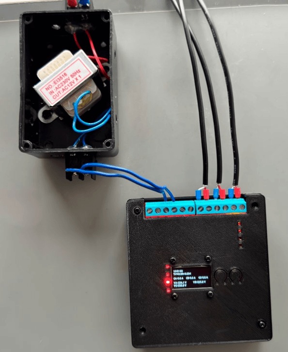
As mentioned earlier, we decided to use a step-down transformer for voltage sampling and the main source of powering the entire system. Finding such a transformer is easy and cheap, but most of these step down transformers take up a lot of space when used in a custom enclosure, as shown in Figure 3. So, it is best that DIN Rail Bell transformers are used in this case to make the setup more clean and safe; such transformers can easily be found online. Moreover, the accuracy of voltage measurements depends on the characteristics of the transformers, including their voltage ratio accuracy, phase shift, and linearity.
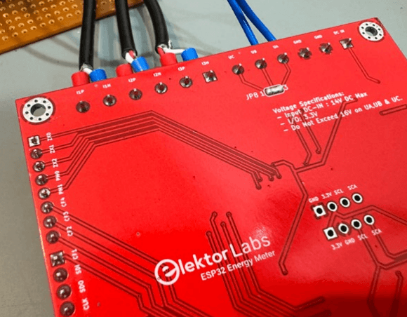
You might have noticed in the images that there is only one transformer attached to the energy meter. As the energy meter was configured to be used in Single Phase mode, by shorting the jumper JP8 on the back side of the PCB, as seen in Figure 4. To operate the energy meter in three-phase mode or to sample voltage from each phase in a three-phase system using three step-down transformers, you must connect the primary sides of three transformers to the respective phases (L1, L2, L3). On the secondary side, connect one end of each transformer’s winding to a common neutral point, forming a star (Y) configuration. The free ends of the secondary windings (V1, V2, V3) will then provide the voltage outputs (UA, UB and UC) on the PCB for each phase. Key considerations include ensuring the transformers are properly rated for the system’s voltage and current, maintaining strict isolation between primary and secondary circuits for safety, and securing a stable and well-balanced neutral connection to prevent measurement inaccuracies.
Setting up with ESPHome and Home Assistant
As part of the development plan, a specific firmware is being created to leverage the capabilities of the energy metering chip and the advanced AI features of the ESP32-S3. Although developing such tailored firmware requires a significant amount of time and is still underway, this does not restrict the usability of the energy meter. The device can be fully functional with existing platforms like Home Assistant, providing an immediate solution for energy monitoring. Therefore, in this article, the focus is on the integration of the ESP32 Energy Meter with Home Assistant and ESPHome. This section will guide you through setting up the energy meter within the Home Assistant environment to utilize its complete functionality.
To set up the ESP32 Energy Meter with the ESPHome firmware and integrate it into Home Assistant, you should start by installing Home Assistant. (See a comprehensive guide in an article by my colleague Clemens Valens .) After that, add the ESPHome integration from the Add-on Store; then create a new project in ESPHome for your ESP32 device. This automatically generates a basic YAML configuration file (such a YAML file specifies a distinct ESPHome project with all the sensors used and many other options). You have to download this default file, before taking the next steps.
Connect your ESP32 to your computer and select the correct COM Port for the ESP32-S3. In the ESPHome dashboard, click Install and choose the .bin file to flash the firmware. Once the firmware is successfully uploaded, and your ESP32 Energy Meter is recognized by Home Assistant, proceed to edit the initial YAML configuration. To do this, open the ESPHome dashboard in Home Assistant, find your device, and click on the Edit option on the energy meter’s card. Replace the existing configuration with the YAML content provided in the GitHub repository . Make sure to properly configure your API, OTA, and WiFi credentials in this new YAML setup.
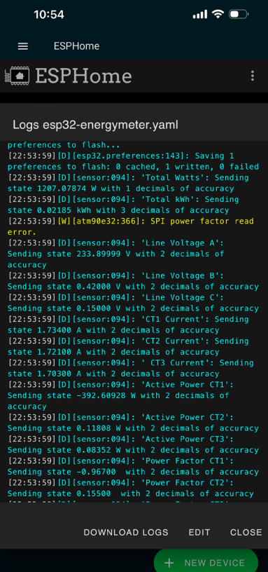
Install the new configuration wirelessly onto your ESP32 Energy Meter. Once this is done, the device will be active and connected. To display the energy meter data on your Home Assistant dashboard, simply assign the ESPHome device to a specific area in Home Assistant. This helps organize your dashboard by grouping devices according to their physical or logical location in your home. For a visual representation of what you can achieve, refer to the Figure 5, which displays the energy meter data on the Home Assistant dashboard.
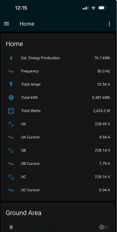
energy data from the ESP32 Energy Meter
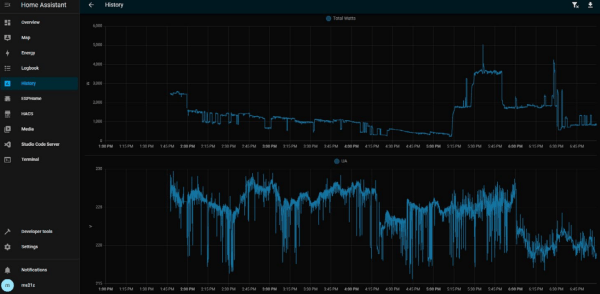
Integrating the ESP32 Energy Meter with Home Assistant not only simplifies the process of monitoring energy usage but also unlocks a suite of powerful features provided by the platform. Home Assistant offers an intuitive interface for real-time data visualization, control automation, and seamless integration with other smart devices in your home. This integration allows for the creation of detailed history graphs and analytics within Home Assistant, providing an in-depth look at power consumption patterns over time, as shown in Figure 6. These insights enable users to make informed decisions about their energy use, identify potential savings, and optimize their home’s energy efficiency.
By following the setup process described above, users can take full advantage of these capabilities, turning the ESP32 Energy Meter into a central component of their smart home ecosystem. This integration not only enhances the functionality of the energy meter but also enriches the overall smart home experience with comprehensive energy monitoring and management tools.
YAML Configuration
The provided YAML configuration sets up the ESP32 Energy Meter with ESPHome, enabling the monitoring of essential electrical parameters like voltage, current, power across all three phases. It leverages the capabilities of the ATM90E32 sensor, with detailed definitions for SPI communication and individual sensors for each phase. This setup not only measures but also calculates total consumption metrics, integrating a daily energy counter for kWh and an OLED display for real-time data visualization. These configurations are made according to the instructions on the ESPHome page for the ATM90E32 sensor.
For ensuring the accuracy of the data reported by the ESP32 Energy Meter, calibration is a crucial step. The specifics of how to adjust the gain settings for current transformers and voltage inputs will be detailed in the upcoming section.
Test Setup and Calibration
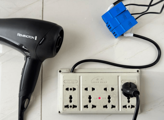
The test setup employed a multi-step heat and speed hair dryer as the load, covering a range from 0.7 A to 8 A. The power cord of an extension power strip was stripped to allow placement of the split coil transformers on the live or neutral wire, facilitating direct monitoring under various conditions as shown in Figure 7.
I conducted the current and voltage calibration of the ESP32 Energy Meter using my UT201+ multimeter. This offers a resolution of 0.001 A and an accuracy specification of ±4% +10 digits for current and a resolution of 0.001 V with accuracy of ±1% +5 digits for voltage. This level of precision is adequate for most projects, but is slightly less precise than professional-grade meters.
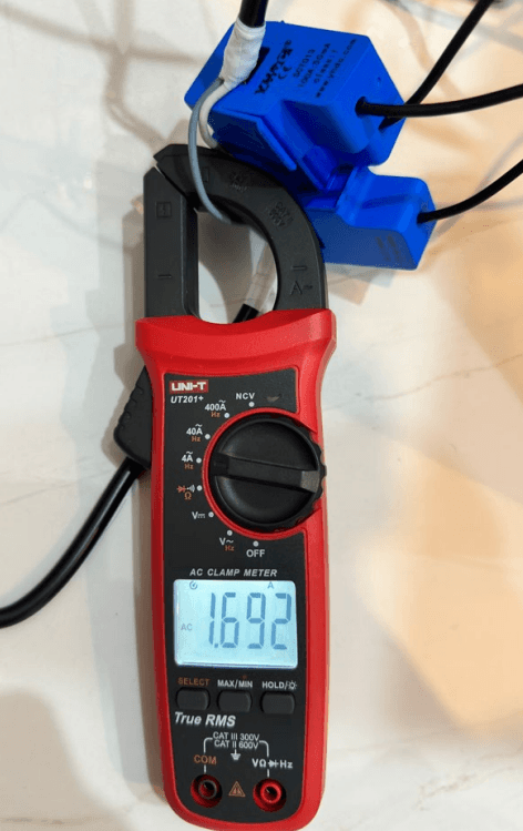
During the calibration, a comparison of current readings was observed: the clamp meter reading was 1.692 A shown in Figure 8, while the readings calculated by the energy meter displayed 1.70 to 1.73 A after calibration, as shown in Figure 9. Given the specifications of the UT201+ and the SCT-013-000, a Class 1 split core transformer which guarantees an accuracy within 1% of the actual value, this small discrepancy falls within the expected error margin. However, for even greater accuracy, a more precise clamp meter could be used.
To fine-tune the ESP32 Energy Meter’s accuracy further, adjustments were made to the gain settings for both voltage and current measurements. For voltage, the sensor was calibrated using the formula:
New gain_voltage = (your voltage reading / ESPHome voltage reading) * existing gain_voltage value
Similarly, for current adjustments:
New gain_ct = (your current reading / ESPHome current reading) * existing gain_ct value
These new gain values were then updated in the ESPHome YAML configuration file, followed by recompiling and uploading the firmware. This process can be repeated as necessary to ensure optimal accuracy. These calibrated values help refine the measurements and are crucial for accurate reporting and analysis in any energy monitoring setup.
WARNING: Working inside a circuit breaker box carries inherent risks, including the potential for electrical shock or fire. It is vital to turn off all power before starting the installation. In most countries, this work may only be carried out by a qualified electrician!
Breaker Box Installation for the ESP32 Energy Meter
Installing the ESP32 Energy Meter into my circuit breaker box proved to be a manageable task that required meticulous attention to detail to ensure both safety and functionality. I started by selecting a circuit with the lowest amp limit. This choice was strategic, as it provided a safety buffer; the circuit breaker would trip in the event of any unexpected surges or transformer failures, thus protecting the system.
Using split core current transformers was particularly beneficial due to their ease of installation. These transformers can be quickly clamped onto any load, but it was crucial to pay attention to the direction of current flow to guarantee accurate readings. It’s important to note that if the direction of the current and the orientation of the current transformer are not aligned correctly, the power readings will appear negative, which indicates incorrect installation.
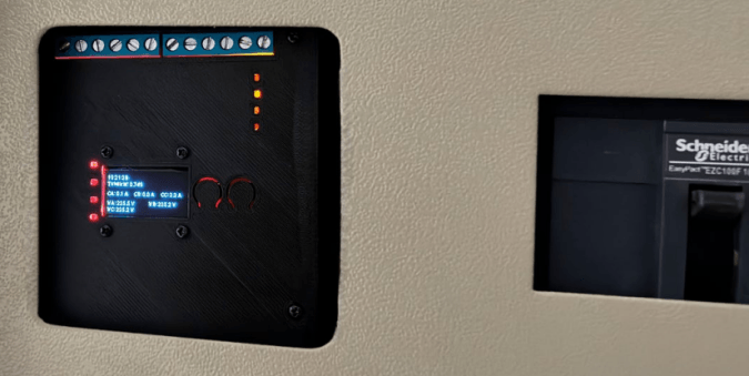
For a visual demonstration of the ESP32 Energy Meter in action within the circuit breaker panel, refer to Figure 10. This image shows the energy meter displaying real-time current, voltage measurements, and the corresponding load in kilowatts, illustrating its functionality in a live setting.
Development and Prospects
While the current software configuration runs on ESPHome, there is ongoing development to expand the capabilities of the ESP32 Energy Meter. The project is looking forward to being integrated with a new firmware specifically designed to harness the full potential of the ESP32-S3 chip. This future firmware is expected to include advanced features such as detailed energy analytics and potentially groundbreaking AI/ML functionalities that could predict energy usage patterns and identify the device according to its load footprint.
Although the core design and operational aspects of the project have been completed, the development of these sophisticated features is a complex and time-consuming endeavor. I am excited about the possibilities and committed to pushing the boundaries of what this energy meter can achieve.
The ESP32 Energy Meter project is continuously evolving, incorporating more features with each update. Community members who are interested in the upcoming AI and ML functionalities, or those who would like to contribute to the development, are encouraged to get involved. Collaboration will help accelerate progress and result in a more robust and feature-rich energy monitoring solution. Keep an eye out for further advancements as the project aims to refine and elevate this versatile energy management tool to new heights.
This article, "Project Update #3: ESP32-Based Energy Meter" (240244-01) originally appeared in Elektor July/Aug 2024. Check out the ESP32-Based Energy Meter Series.


Discussion (0 comments)