Fast Fourier Transform (FFT) on the ESP32
on

In this article, we investigate what goes into running a daunting math task such as FFT on an Espressif ESP32 development board, admittedly with a little help from a library, a Pmod I2S2 module, and a dedicated program.
The Fourier transform is one of the important topics in signal processing as a means of mapping a signal from the time domain into the frequency domain. Any signal of any shape can be represented by an infinite sum of sine and cosine waveforms. The Fourier transform is used to find the components of these series when analog signals are used. The result is the frequency spectrum of the input analog signal, where each of its frequency and amplitude values can be extracted.
The discrete Fourier transform (DFT) is a transformation just like the Fourier Transform, but it is used with digital signals. i.e., DFT is the discrete version of the original Fourier transform. Fast fourier transform (FFT) is an algorithm used to compute the DFT quickly and efficiently. i.e., FFT is an implementation of the DFT that produces almost identical results, but is much quicker and more efficient.
Both DFT and FFT are complex processes, requiring good mathematics to understand them. Although there are several FFT algorithms, one of the most commonly used was developed by Cooley-Tukey, which is a divide-and-conquer type algorithm. This algorithm breaks the DFT down into smaller parts.
Editor’s Note: This article (230623-01) is an excerpt from the 254-page book, Practical Audio DSP Projects with the ESP32 (Dogan Ibrahim and Ahmet Ibrahim, Elektor, 2023). The excerpt was formatted and lightly edited to match Elektor Mag’s editorial standards and page layout. The authors and editor have done their best in such editing and are happy to assist with queries.

Why FFT?
The FFT algorithm is so efficient and fast that it can be implemented with most microcontroller systems. It enables one to see which frequencies are present in any digital signal, and also which of these frequencies are the dominating ones. In an FFT display, what you see is the frequency at the horizontal axis and the amplitude at the vertical axis. A graph of one or more spikes is shown.
A tall spike indicates a frequency that’s dominant in the input signal. The most dominant spike represents the fundamental frequency of the input signal. The other spikes are in the form of harmonics, which occur at multiples of the fundamental.
If the input signal is a sine wave, then there’s only one spike with the same frequency as the input signal. If the input signal is a square wave, then a number of spikes with decreasing amplitudes are shown at different frequency points. The FFT algorithm works with a finite number of input samples (called the length), which need to be multiples of 2 (e.g., 32, 64, 128, 256, etc.). In general, the more samples, the slower the algorithm and also the more required, as more processing is needed. However, more samples will yield more accurate results.
In this article, we will be developing an FFT program using Phil Pschatzmann’s Arduino Audio Tools library, which is based on the AudioRealFFT class. The results will be displayed in Serial Monitor with the frequency, its magnitude, and the musical note corresponding to the frequency. More details are available on a dedicated web page.
Hands-On FFT of an Input Signal
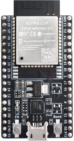
In this project, the Pmod I2S2 module is used, which is cheap and widely available from various sources. A signal (sine wave, square wave, or any other waveform) is injected into its input port (blue connector). The fundamental frequency, magnitude, and musical tone frequency nearest this frequency are all displayed in Serial Monitor. The aim of this project is to show how the Arduino Audio Tools library can be used for an FFT application running on an ESP32. The dev board used throughout the abovementioned book is the Espressif ESP32-WROOM-32D pictured in Figure 1. It’s breadboard compatible and has 5 mm × 27.9 mm dimensions.

dev board.
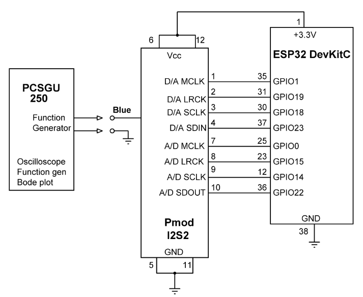
Figure 2 shows the project’s circuit diagram. The Pmod I2S2 module receives audio signals from the PCSGU250 signal generator or an equivalent instrument in your lab. Notice that, even though only the ADC part of the Pmod I2S2 is used, the connections for both the ADC and DAC are shown in the schematic. The program processes the input samples and displays the results in Serial Monitor.

Listing 1 shows the FFT program. This program is included in a software archive released in support of the Practical Audio DSP Projects with the ESP32 book. The archive is available as a free download from the “Books” section of the Elektor Store website. Once on the web page, scroll to “Downloads” to locate the Software_Practical Audio DSP Projects with the ESP32 (.zip file, 62 MB) download, and save it on your system. Unzip the archive and locate the FFT.ino program in the chapter 14 material.
/***************************************************************
* FAST FOURIER TRANSFORM
* ======================
*
* This program uses the Arduino Audio Tools library to display
* the FFT components of an input signal.
*
* Author : Dogan Ibrahim
* Program: FFT
* Date : May, 2023
*
* (This program is a modified version of the program developed
* by Phil Pschatzmann)
***************************************************************/
#include "AudioTools.h"
#include "AudioLibs/AudioRealFFT.h"
uint16_t sample_rate=44100;
uint8_t channels = 2;
I2SStream in;
AudioRealFFT fft;
StreamCopy copier(fft, in);
//
// Display fft result on Serial Monitor
//
void fftResult(AudioFFTBase &fft)
{
float diff;
auto result = fft.result();
if (result.magnitude>100)
{
Serial.print(result.frequency);
Serial.print(" ");
Serial.print(result.magnitude);
Serial.print(" => ");
Serial.print(result.frequencyAsNote(diff));
Serial.print( " diff: ");
Serial.println(diff);
}
}
void setup(void)
{
Serial.begin(115200);
//
// Configure in stream
//
auto configin = in.defaultConfig(RX_MODE);
configin.sample_rate = sample_rate;
configin.channels = channels;
configin.bits_per_sample = 16;
configin.i2s_format = I2S_STD_FORMAT;
configin.is_master = true;
configin.port_no = 0;
configin.pin_ws = 15; // LRCK
configin.pin_bck = 14; // SCLK
configin.pin_data = 22; // SDOUT
configin.pin_mck = 0;
in.begin(configin);
//
// Configure FFT
//
auto tcfg = fft.defaultConfig();
tcfg.length = 8192;
tcfg.channels = channels;
tcfg.sample_rate = sample_rate;
tcfg.bits_per_sample = 16;
tcfg.callback = &fftResult;
fft.begin(tcfg);
}
//
// Copy input signal to fft
//
void loop()
{
copier.copy();
}
At the beginning of the program, header files AudioTools.h and AudioLibs/AudioRealFFT.h are included. Streams fft and in are defined. Inside the setup() function, the I2S stream in (in RX_MODE) is configured by specifying the ESP32 GPIO ports it is connected to. Also, the FFT is configured by setting the length to 8,192 samples. The callback function is passed the name fftResult so that the FFT results are available at this function. Function fftResult() displays the frequency, magnitude, and the musical tone nearest this frequency, together with the difference between the two frequencies.

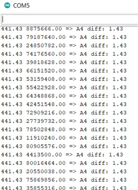
Sample output is shown in Figure 3, where the input was a sine wave with a frequency of 440 Hz. Now, is that fast or what?
Questions or Comments?
Do you have questions or comments about this article? Email the author at d.ibrahim@btinternet.com or contact Elektor at editor@elektor.com.


Discussion (0 comments)