

IKEA Lamp Hack
on
As an engineer, I like working out solutions to problems; that’s what motivates me. Some time ago I faced an unexpected challenge when my son gave me a NeoPixel Jewel 7 board [1] from Adafruit. It was a leftover from a project he'd been working on at university. This small, circular circuit board can be seen in Figure 1. The board is fitted with seven programmable NeoPixel RBG LEDs in and SMD outline. My only thought was…what on earth could I use it for?
NeoPixel + Arduino
WorldSemi Co. has been supplying RGB LEDs with an integrated controller in its product range for some time now. These feature a three-wire interface, allowing them to be easily "daisy-chained" for larger display applications. Each RGB LED can be addressed individually via a single serial data signal. You will get lots of hits, mostly from the Far East, when you enter the terms "NeoPixel" or "WS2812B" on eBay. Since I had already developed a whole series of Arduino projects, I knew it would not be difficult to control these LEDs with the help of the appropriate library from Adafruit. My first impressions of these LEDs were recorded on my retina…they are quite bright at full power, so please be careful not to stare at them directly!
The Arduino boards are a good general-purpose controller solution for many experimental setups but, if you need an Internet connection, it is better to use a different solution. At the time I was working with an ESP8266 MCU from Espressif in the form of the D1 mini Pro from WeMos. It seemed to me that this board, together with the NeoPixel LED board, would make for a good combination. To make sure the finished light source blended well into a domestic environment, it would be necessary to build it into a suitable housing.
Lamp tweaking
My solution to the problem was to modify a standard IKEA Grönö lamp for the housing. This lamp (Figure 2) only costs € 6.50 in Denmark (£7 in the UK), making it an ideal candidate for hacking. Should I end up destroying it in the process, then I haven’t really lost much — this should always be your number one consideration before you set about hacking anything.
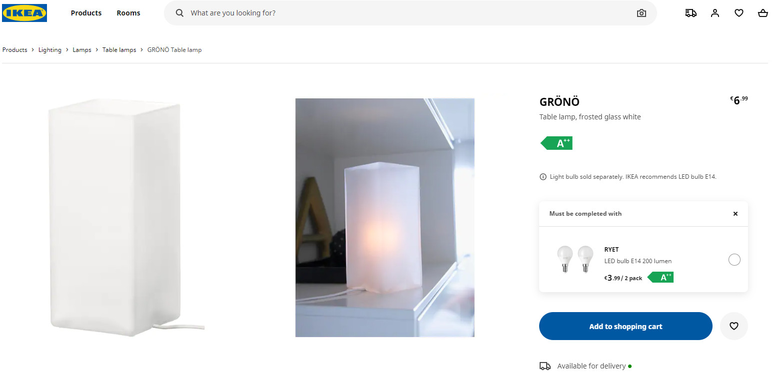
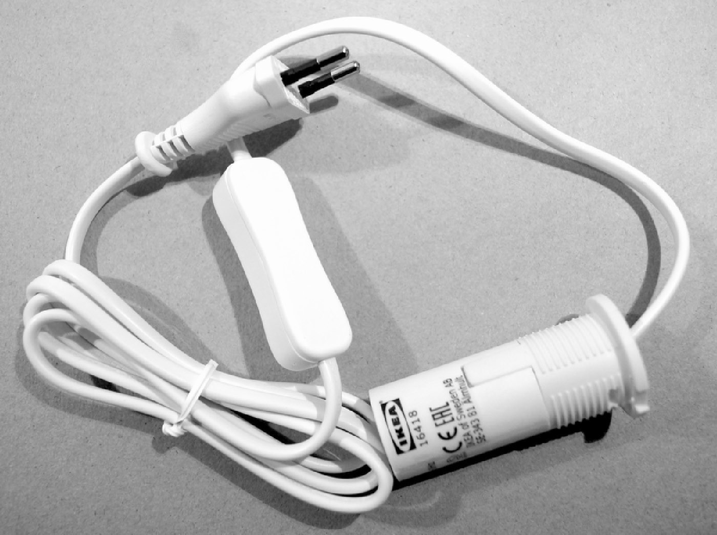
Figure 3 shows the lamp internals; it’s just an E14 style lamp holder and power cord with an in-line power switch.
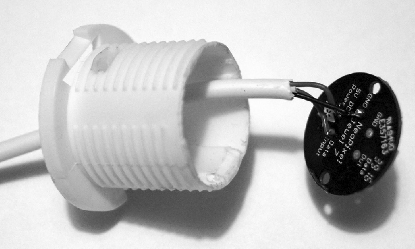
We will only need three wires to connect the ESP8266 to the NeoPixel board. The lamp holder base can be modified and the power cord discarded. The board is then fixed on top of the cut-down lamp holder base with glue. Finally, the power cord is replaced by three short leads (Figure 4).
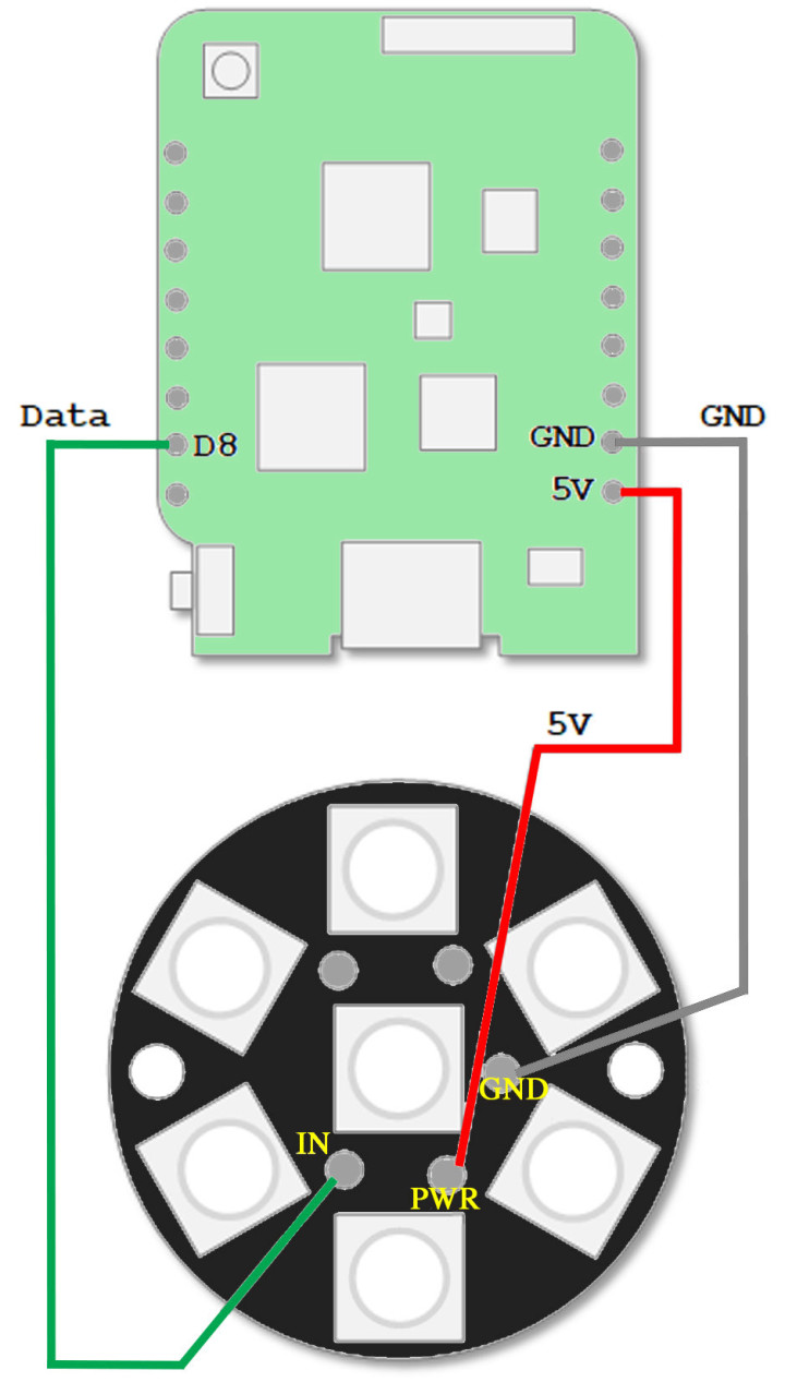
The lamp controller circuit (Figure 5) could hardly be simpler. In addition to the NeoPixel board and the ESP8266, the lamp requires a 5 V, 500 mA mains adapter power supply with a micro USB plug. The rest of the project is purely software. The NeoPixel board is fitted with seven RGB LEDs, each with its own in-built controller in SMD 5050 format. You can also buy these LEDs individually under the designation WS2812B and thereby make almost any complex string or matrix arrangement. Each RGB LED takes up to 60 mA at full brightness, delivering a maximum luminous flux of 20 lm. You can hook them up in series and address them individually by shifting the RGB brightness data serially into the chain at one end. This makes them very easy to control.
Software
An important attribute of the WeMos D1 mini Pro board is that it is supported by the Arduino IDE. Using the Arduino IDE has its advantages and disadvantages — what I find particularly relevant is that it allows me to get a project up and running quickly and without too much fuss. Before we start with the software for this IKEA hack, it is necessary to do a little preparatory work:
- Install the Arduino IDE.
- Include support for the ESP8266 MCU in the IDE.
- Install the Adafruit-NeoPixel library within the Arduino IDE.
- Install the Arduino ESP8266 file system uploader (for SPI flash).
The software may seem a little complex given the simple task of controlling the LEDs, but the reason for the complexity is that an ESP8266 has built-in Wi-Fi support. If we want to make use of it, we will need some code. The software provides the following capabilities:
- Creation of special lighting effects.
- Internet connectivity via Wi-Fi.
- Web server for lamp configuration.
The lamp can also be operated "offline" or in standalone mode. In this case, it will run through the colors of the rainbow at a predefined rate (e.g., 20 ms for each of the 8x8x8 color levels). If you want to be able to configure the lamp during operation, you must activate the Wi-Fi link so that the NeoPixel lamp can communicate via your local network. The necessary parameters for the Wi-Fi can be hard coded in the source code. This means any changes to the network parameters require a recompilation of the WeMos firmware. Otherwise, they can be defined during the lamp power-on ‘boot’ period. Once the lamp is connected to the Wi-Fi network it will be possible to carry out the following operations:
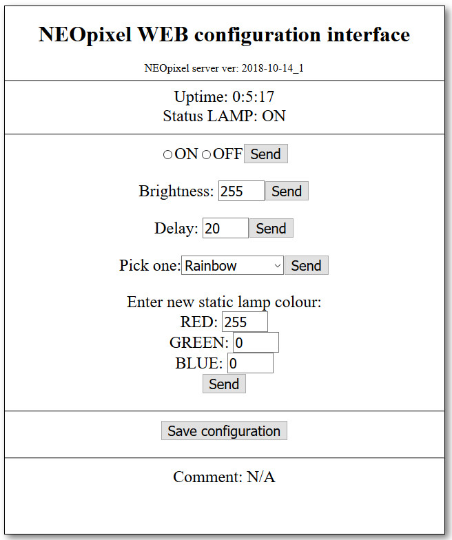
- Turn the lamp on and off.
- Control the brightness.
- Change the delay time between color cycling.
- Select color cycles (currently rainbow, rainbow cycles, static, candle flicker, and fading).
- Set a fixed lamp color.
These operations can be performed via a very simple web interface (Figure 6).
The HTML code for the web page is generated using the getPage(string str) function.
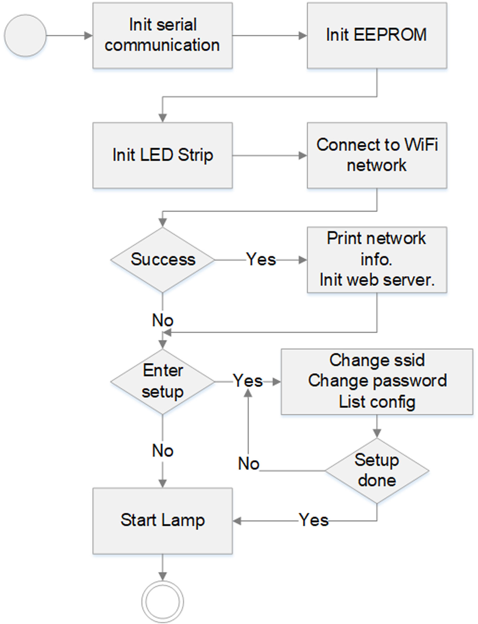
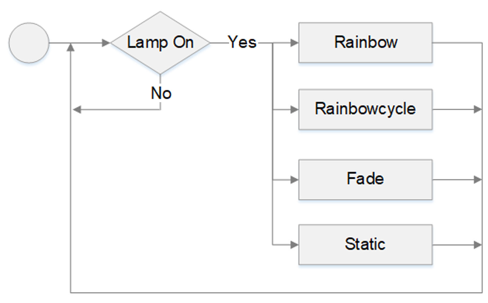
All of this is handled in the software and, because of this, is not so easy to make changes to. However, it works well enough for our purposes. The web configuration interface updates the NeoPixel lamp via an HTTP POST request method. The basic procedure is described in my book, IoT Home Hacks with ESP8266. The software is structured in much the same way as for other similar projects I've developed. Figure 7 shows the software flow chart during setup with Figure 8 displaying the same for operation or mode selection.
I quickly discovered that the fade function (increasing and decreasing brightness) requires a little more consideration. If you control the lamp brightness using values that correspond to a linear ramp function, the change in brightness is not satisfying. As shown in Figure 9, it's better to use a function that approximates a sine wave to produce a more gentle change in brightness. This brightness curve was simulated in Excel and the values implemented as an array byte fadeInterpolation[]. These values can of course be changed.

The article "LED-Dimmers" in Elektor 9/2018 describes this effect. The relation between the actual change in a physical stimulus and the perceived change is a psychophysical property characterized by the Weber-Fechner law.
Using the Lamp
As soon as the programmed WeMos board is powered on, the software will boot up and enter its switch-on cycle.
Wi-Fi connection (blue light)
In this phase, a connection with the Wi-Fi network is attempted using the network parameters programmed in software. During this phase, each of the LEDs will flash blue one after another.
Wait (red light)
After attempting to connect with the Wi-Fi (successfully or unsuccessfully), the board will look for user interaction via the USB port. During this period, the LEDs will flash red one after another. When an interaction is detected all the LEDs will go off. If after ten seconds no interaction is detected, the lamp begins running its pre-configured lighting pattern. After switch-on and with an active Wi-Fi connection, it is possible to control the lighting effect or operating mode of the NeoPixel lamp.
A different web interface
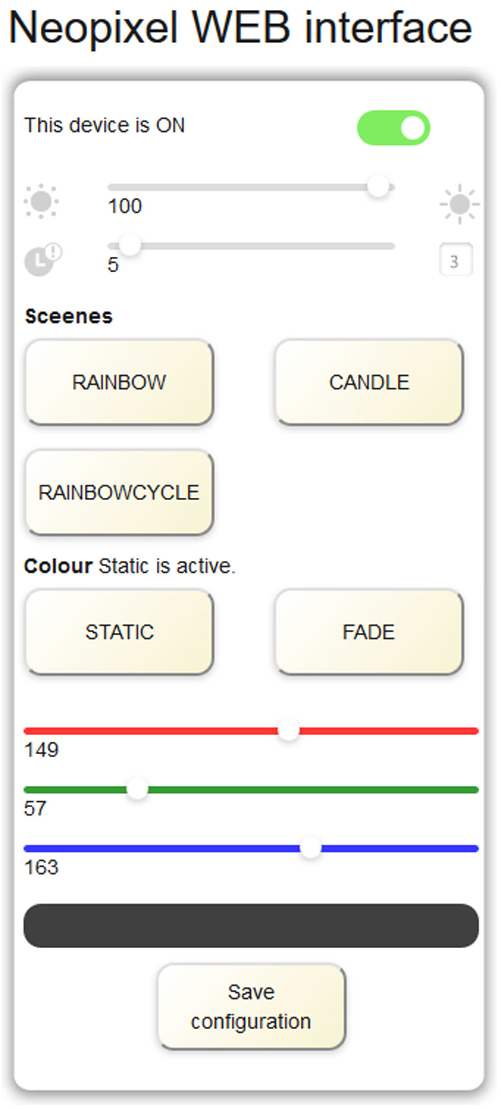
Once I had got this far with the project, I showed the results of my efforts to my son. He has a master's degree in interactive design and was not at all impressed with the design of the web interface. He went on to develop a new design (Figure 10), that proved difficult to implement in "hard" code.
Instead, a design using HTML, CSS, and Javascript was developed. This is where the SPI flash file system comes into play. The ESP8266 MCU provides at least 14 MB of flash memory that can be used via the SPIFFS file system. In my book you will find information on:
- Uploading files to SPIFFS.
- Storing files in a PC for uploading.
- Installation of the necessary software for the Arduino IDE.
If you’ve installed it correctly, your Arduino software directory should look similar to Figure 11.
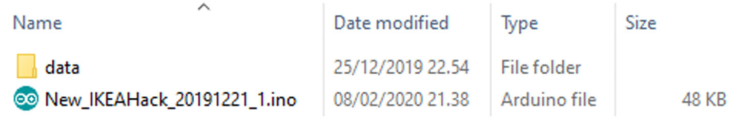
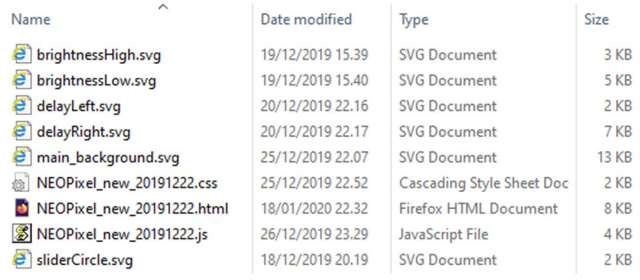
Figure 12 shows the files for the web interface contained in the data folder. The latest version of the software can be downloaded free of charge from the Elektor website for this article. You will notice that the NEOPixel_new_20191222_load.js file is not listed in the data directory. These functions are coded directly in the ESP8266 software. This allows the ESP8266-MCU to configure the Web interface upon power-up using the parameters stored in the EEPROM.
The web interface concept has been designed for smartphone screens in portrait-display orientation. Since the NeoPixel lamp can be configured by sending it HTTP POST requests, it is also possible to control the lamp via the OpenHAB home automation solution — but that's another story.
A successful IKEA lamp hack
Working with the NeoPixel Jewel board has led me to explore many different areas that I wasn't familiar with before the project started. Overall the result is quite satisfying; this IKEA lamp hack with its shoe-horned NeoPixel board has been lighting up my living room now for over a year.
----------------------------------------------------------------------------------------------------------------------
Want more great Elektor content like this?
--> Take out an Elektor membership today and never miss an article, project, or tutorial.
----------------------------------------------------------------------------------------------------------------------
Discussion (26 comments)
HaSch 4 years ago
My Fritzbox has a password of 20 characters and I think most Fritzboxes have. So, the sketch can not used with those very popular routers. I think the possibility of setting up WiFi credentials with exact 20 characters (or more) would be necessary.
HHS 4 years ago
This present length were sufficient at the time I made the software.
Please adjust
#define PASSWORD_POS 40
in accordance with the increased
#define SSID_LEN 21
Do also adjust the declarations of
char ssid[21]
char password[21]
in accordance with the new length of the SSID and password.
HaSch 4 years ago
HHS 4 years ago
It is due to an assignment in the function "NEOPixel_load_script ()" in line 288 and 290 which is not correct.
Please find attached a complete set of updated files.
In order to update the lamp please first perform a "Sketch data upload" and then upload the corrected .ino file.
HaSch 4 years ago
OK, I tried to get it work. I merged your code into mine, renamed the .css, .html and .js files uploaded it and gave it a try. Unfortunately it doesn't work. When the webserver is started, I see as the 1st text line "This device is ", "ON" or "OFF" is missing and the switch is always off.
Thank you very much.
HHS 4 years ago
So either you should only change the .ino file in function "NEOPixel_load_script ()" and keep the rest of the files unchanged or you should include the complete package as shown above.
In order to keep track of changes I prefer to make a new set of files.
HaSch 4 years ago
But did you ever try to change WiFi credentials?
First of all, with your original code it isn't possible to send commands to the board using serial console of Arduino IDE. I repaired while changing line 1232 in setup routine of your original Arduino sketch.is going to
if (inByte != 13)    // avoid storing CR to inData
    {
         inData += char(inByte);
    }
Now the sketch understands the commands. All tests I made are described here and are made with lightly modified original sketch. All modifications you can find here.Because my Fritzbox password is 21 characters I changed the following lines 56 to 58:lines 76 and 77:
the buffer size (114):and further lines 1251 and 1302 in setup:Changing of WiFi credentials now seems to work fine. I see new ssid and new pssw in serial console if I send command "list". But that's all! If I restart the board it can not connect to that WiFi. If I clear EEPROM using a clearing sketch, flash your sketch again and keep WiFi change untouched connecting is no problem.
Can you tell me what's going wrong?
Best regards
Hans
HHS 4 years ago
Have you entered your SSID and password into the code in line 76 and line 77, or do you enter it via the serial interface only?
The following is just to be sure that you get the correct read outs:
When powering on the device (with #define DEBUG 1 ) you should see what is stored in the EEPROM.
The SSID and the password should also be listed - I know not the best protection, but DEBUG is on.
When entering new SSID or new password you should be offered the possibility to save and see a confirmation when done:
===================
Valid commands: ssid, pssw, list, done.
SSID:
Enter new SSID string (must be less than 20 char)
New SSID: XXXX
Save new SSID (y/n)
New SSID saved.
Valid commands: ssid, pssw, list, done
===================
There is a timeout for entering the new SSID and for saving the SSID.
If you experience the same I need to investigate more.
HaSch 4 years ago
What you wrote about the commands and saving SSID and password is correct. So, I experienced the same as you. If I try to change SSID and Password it works, but after that the board isn't able to connect to the same WiFi as before.
HHS 4 years ago
Beside that I don't have more comments to that behavior - except enable the debug feature in the Arduino IDE.
Tools -> Debug port -> serial
Tools -> Debug level -> WiFi
As I have not done much in this I cannot advise, but feel free to list your findings..
HaSch 4 years ago
I also tested another board but it is the same bug. Is your sketch doing well with your board while changing WiFi credentials?
Tomorrow, I will try your suggestion with the debug port.
HHS 4 years ago
That's good but still it is a nuisance.
No problems changing SSID or password with my board or WiFi router.
Again both is below 20 characters.
In the function bool doWifiConnect() you could add the following
Serial.print("** WiFi status: "); showWiFiStatus( WiFi.status() );
just before the function return false.
HaSch 4 years ago
The board seems not to be able to find the WiFi which before it was connected to. Maybe the routine added a hidden character to the SSID while storing to EEPROM? CR, blank, ...
[EDIT]
I think I found the bug!!!
It was indeed a CR added to SSID and password that prevented the board to connect to the WiFi after changing WiFi credentials. I changed the corresponding lines and now it works!
// Save new SSID
memcpy(ssid, Buffer, ByteCount+1);
for( j = 0; ((j < SSID_LEN) && (Buffer[j] != 0x00) && (Buffer[j] != 13)); j++ )
  {
    EEPROM.write(SSID_POS+j, ssid[j]);
  }
EEPROM.write(SSID_POS+j, 0x00);
EEPROM.commit(); // Needed in order to save content to flash.
and also:By the way: It's a nice project you have done and a pretty piece of software! I like it very much. In the future I will see if it is possible to integrate in Homebridge to create Homekit compatibility. There are plugins for ESP8266 in Homebridge and I will do a few tests with it.
HaSch 4 years ago
When the server is started, the field containing the choosen color is black. After turning the color slider (e.g. red) the field is turning into the same color (red). Pressing refresh button turns on black again. It would be nice if the field starts in the choosen color and remains in this color..
HHS 4 years ago
I was awaiting any more findings by you related to the WiFi issue, before I would release a new software.
I will submit the changes within the coming week.
Thank you for taking your time to go through my software.
HaSch 4 years ago
HHS 4 years ago
Changes are marked in the software if you want to update your own version.
HHS 4 years ago
Changes can be seen in the header of the software.
Each change is also marked in the software.
HaSch 4 years ago
I tested your changes and it's working fine!
But there are some things to do to get it better. I would like you to pay attention at two little issues:
With serial console of Arduino IDE 1.8.13 it isn't possible to send commands after entering the command line mode. You have to change your line 1254 fromto
if (inByte != 13)    // avoid storing CR to inData
  {
    inData += char(inByte);
  }
to get it work.Also, I improved the following two lines to get a correct information (1261/1312):
Serial.print(" Enter new SSID string (must be less than "); Serial.print (SSID_LEN); Serial.print (" char)\n");Serial.print(" Enter new password string (must be less than "); Serial.print (PASSWORD_LEN); Serial.print(" char)\n");Best regards,
Hans
PS: I also corrected the typo sceene -> scene and the English "colour" to the US American "color" as it seems to be more common for me ;-)
HHS 4 years ago
Nice to hear that the changes are working as intended.
Since I'm Danish, English is not my native language. I do therefore have an English reviewer. This is why we stick to colour and not color.
And the reviewer does not go through my code. ;-)
Regards and take care.
HHS
HaSch 4 years ago
Have fun!
HaSch 4 years ago
HHS 4 years ago
I must admit that I have no Apple experience what so ever, but I'm impressed that you have taken the time to implement the Apple Homekit support.
i will pass it on to my son who uses the Apple framework at home.
hello_world.c 4 years ago
Also, a tip for your future projects: Instead of messing with SSID and password settings in your application, I can highly recommend Wifi Manager:
https://github.com/tzapu/WiFiManager
It spans a captive portal/AP when unconfigured which allows you to connect with any device and select a WiFi network to connect to and enter the password. It is then saved internally and automatically used next time it starts up. It is incredibly easy to use (but must have been insanely hard to develop) and saves a whole lot of headache!
Cheers,
Chris
Content Director, Elektor 4 years ago
HHS 4 years ago
Thank you for your comments, they are highly appreciated. Since I have transferred the work done in the “IKEA hack” exclusively to elektor, they should in the end decide what to do.
From my point of view it would be fine if you make a reference to me, elektor and this article, as long as you don’t use it commercially.
I’m also pleased to see that what has been accomplished here can be used by others.
Thank you for the reference to the WiFi manager. I’m aware of its presence and have been tempted to include the work, but decided not to. Most of my designs should fulfill a purpose right away except the IKEA hack, which evolved into something more thanks to my son. It would have made sense to include the WiFi manager in the updated WEB interface – but then I should also have updated the SD-Card flash file system.
Good luck with your project and as mentioned by ElektorMarketing, please show the result.
Regards and take care.
HHS