
Miniphonic: An Arduino-Based Audio Synthesis Platform (1)
on
Thanks to software frameworks and libraries that have become quite powerful over time, even with a compact and inexpensive system, it is possible to achieve complex functions. In this project, we use an Arduino Uno R4 board and other hardware to make a rather versatile and performing sound synthesizer and MIDI sequencer. In the first part of this series on audio synthesis, we describe the block diagram and the main functions of the Basic Synth software.
Audio Synthesis Platform
Some of you may remember the old SN76477, the famous complex sound generator from Texas Instruments. Originating in the 1970s, it allowed the creation of a variety of sounds such as gunfire, steam locomotives, space sounds, and much more, including small musical synthesizers.
It was this last feature to be particularly attractive. I had been wanting to build a small sound synthesizer for some time, when I accidentally stumbled upon Tim Barras’ amazing Mozzi library, which allows you to implement synthesizers and drum machines simply by using an Arduino Uno R4 Minima board and a few other components.

Not only that, along the way, I also found Staffan Melin’s OscPocketO software, a valuable sequencer based in turn on the Mozzi library. So, it was decided to abandon the old SN76477 in favor of the latter solution and MiniPhonic Audio Synthesis Platform was born, a hardware sound synthesis platform whose main features are:
- LCD, 20x4
- 4 programmable potentiometers for changing parameters in real time
- Input/Output for synchronization with another synthesizer
- MIDI input/output
- Monitor amplifier for headphones
- 4-pole LP filter for the on-chip DAC
- Housing for Arduino Uno R4
The audio synthesis platform is structured on two PCBs: the Main board and the Display Board connected via a 14-pin flat cable. Figure 1 shows the block diagram of the synthesizer, which is useful for understanding the operation and following the audio stream. The latter, initially in numerical format, is converted into an analog signal via a 12-bit, on-chip DAC converter connected to the low-pass filter LPF.
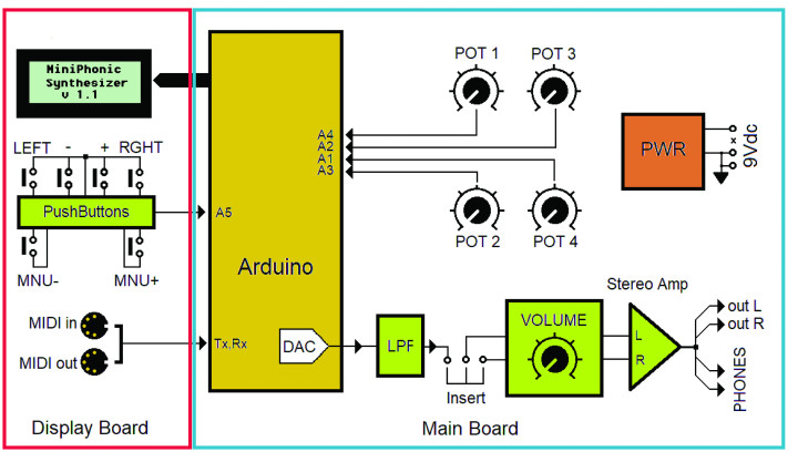
At the output of this filter is a decoupling resistor, which allows audio from other synthesizers to be fed via the Insert connector. This connector allows the insertion of an external effects processor, such as a reverb. External effects processors often have a stereo output, which is why both the volume pot and the monitor amplifier are stereo. However, on the Main Board, it is possible to bypass the Insert pins to configure the entire audio chain in mono mode. To do this, simply short SJ3 and SJ4 pads on the PCB (shown in the next installment of this article) with a drop of tin.
The line outputs OUT L and OUT R are also connected to the monitor amplifier. The platform offers two main applications:
- Basic Synth: a basic monophonic synthesizer that uses the MIDI input to connect a standard keyboard and play in real time.
- Sequence: designed as a stand-alone sequencer with the ability to drive other synthesizers via the SYNC or MIDI OUT connector.
These applications are available for download at the Elektor Labs page for this project. Let’s look at the first of them, in detail.
Basic Synth
The block diagram of the Basic Synth application, shown in Figure 2, takes the classic structure of a synthesizer and is based on a software structure called Synthesizer Chain (see the nearby text frame), which is found starting at about line 920 of the code.
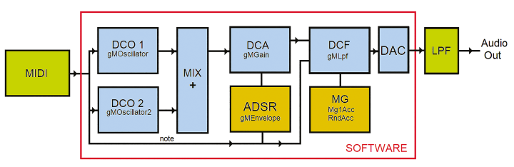
In detail, the operation gMOscillator.next() * Lv1 >> 4 multiplies the samples generated by the DCO1 oscillator gMOscillator.next() by the value of Lv1, scaled appropriately via the >> 4 operator. This operation simulates the operation of a volume potentiometer, where the signal is represented by gMOscillator.next() and Lv1 indicates the angular position of the potentiometer. The same operation is performed for the second oscillator, DCO2.
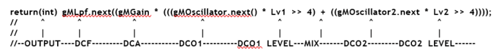
Another block in the schematic is the mixer (MIX), realized simply by the + (sum) operator, which adds the samples from the two oscillators. The DCA (Digital Controlled Amplifier) block is implemented by multiplying the sum of the two oscillators by the variable gMGain, which is updated dynamically by gMEnvelope.next(). This component represents an ADSR envelope generator.
It is important to note the .next members, which represent samples of the audio or control streams. In the block diagram, we can note the unusual position of the DCF, which follows the DCA rather than preceding it; this is due to the numerical format of the audio stream that better fits the DCF that was originally designed to run on the Arduino Uno R3. (Ideally, the libraries would be rewritten in a format suitable for the Arduino Uno R4, to take full advantage of the features of the Arm Cortex4 RA4M1 processor, which, moreover, also has an additional DSP instruction set.)
On the block diagram, we observe that the MIDI input is connected not only to DCO1 and DCO2 — to transmit note codes and determine oscillator frequency based on the MIDI note number — but also to the ADSR envelope generator. The latter uses the Note On and Note Off codes to start an envelope cycle on the activation or release of a note. Note codes can also be used by the DCF to change its cutoff frequency by enabling the Manual KBD Tracking mode. In this way, the DCF acts as a real tracking filter. MG in the block diagram stands for Modulation Generator.
User Interface
Let us now see how the User Interface was configured for this audio synthesis platform application. The display is divided into two sections: the first two lines show the captions associated with the four potentiometers, indicating the current Panel.
Four Panels are available (PANEL_MAIN, PANEL_ADSR, PANEL_MIXER and PANEL_FILTER) accessible through the Tools menu, which will be described later. The menus can be reached via the appropriate MNU+ and MNU- buttons, while instead the LEFT and RGHT buttons select a submenu. VAL+ and VAL-, on the other hand, allow parameters to be changed.
Let us therefore see the items of the main menu:
WAVEFORM: this menu allows, using VAL+ and VAL- to choose from five waveforms for the DCO1 oscillator: Sine, Triangular, Sawtooth, Square and an atypical one called Phasor.
FILTER mode: using VAL+ and VAL- we can change filter operation mode. We can choose between Manual KBD Tracking in which the gMFilterCutoff frequency of the DCF is shifted by the MIDI note number, Random MG1 where the frequency is shifted randomly and with speed set by MG1, Mod MG1 in which a triangular shape modulation is applied with speed always set by MG1 and finally Fast, like the previous one, but with fixed speed.
WAVEFORM2: same functionality as WAVEFORM, but acts on the second oscillator DCO2.
DETUNE 2: fine tuning of the DCO2 oscillator (VAL+ and VAL-). A number between 1 and 2 slightly deviates the frequency of DCO2 so as to create a chorus effect with DCO1.
TRANSPOSE 2: Transposition of DCO2, again using VAL+ and VAL-.
TOOLS: From this menu you can choose between the submenus Save, i.e., saving the entire Synth setting, Load i.e., loading the setting, and Panel in which the Panels are accessible. The submenus are chosen via the LEFT and RGHT buttons.
In PANEL_MAIN we find:
- FREQ ATTACK
- RESO RELEAS
where FREQ and RESO pertain to the cutoff frequency and resonance of the filter, ATTACK and RELEAS belong to the ADSR envelope generator, that is, the attack time and release time. In the PANEL_ADSR, on the other hand, we find all four parameters of the ADSR. In particular, the SUST_LEV and DECAY parameters allow us to create percussive sounds:
- ATTACK DECAY
- SUST_LEV REL
From the PANEL_MIXER we can dose the levels of the two oscillators and the frequency of the modulation generator MG1 via FRM1:
LEVL_1 FRM1
LEVL_2 ----
Of course, it is possible to increase the number of Panels by expanding the DrawPanel() function in the code.
The Firmware Basic Synth
In setup (around line 806) we find all the instrument setup as well as the initializations. First we set up the display with gUILCD.begin(20, 4). We then find the credits and the version number of the Software as well as the MIDI initialization, preceded by the connections to the MIDI library of HandleNoteOn and HandleNoteOff handles and the start of the MIDI library in MIDI_CHANNEL_OMNI mode, in which all MIDI channels 1 to 16 are received:
// Connect the HandleNoteOn function to the library,
// so it is called upon reception of a NoteOn.
MIDI.setHandleNoteOn(HandleNoteOn);
// Put only the name of the function
MIDI.setHandleNoteOff(HandleNoteOff);
// Put only the name of the function
// Initiate MIDI communications,
// listen to all channels
MIDI.begin(MIDI_CHANNEL_OMNI);
The HandleNoteOn function is used by the keyboard connected to the MIDI IN port, and plays a note upon receipt of the NoteOn message; this note will persist until the NoteOff message is received, or until the gMSustainTime expires, via the HandleNoteOff function.
From line 834 or so follow all the arrangements of the Mozzi library, so that the synthesizer can begin playing immediately. The user interface (User Interface Draw) is started around line 868 or so, and immediately after that the Mozzi library is started:
UIDraw();
startMozzi(CONTROL_RATE)
In the updateControl() function, MIDI port querying with MIDI.read(), envelope updating with gMEnvelope.update(), and button handling with the UIHandle() function take place.
STEP RANDOM GENERATOR or MG1 is then executed, which is responsible for generating a random sequence of data and a triangle wave, resulting in RndAcc and MG1acc, respectively.
Both values will later be used to modulate the filter. The frequency is determined by the modulation generator MG1, the value of which is controlled by the potentiometer FRM1, located in the third panel of the menu. It is important to note that this frequency is proportional to the CONTROL_RATE, already introduced in the StartMozzi function.
There is also an implementation of a second modulation generator, MG2, which can be concatenated with the first one for further modulation possibilities. Finally, the audio stream is updated via the updateAudio() function. This is the most important function since it encapsulates the processing of the audio stream, i.e., the Synthesizer chain we saw at the beginning. It concludes the loop that contains the main call to the Mozzi library audioHook().
The Sound Synthesis, in Short
Sound is mainly characterized by frequency — the number of periods per second — and is measured in Hertz (Hz). For example, 100 Hz means 100 periods per second see Figure A, or 100 oscillations per second; in the case of a string it means that it will vibrate 100 times per second.

If our frequency takes the value of 440 Hz then we are playing a natural A, if the frequency drops to 220 Hz then we are still playing an A, but an octave below. 880 Hz, on the other hand, corresponds to A one octave higher. Furthermore, the sound is characterized by timbre, that is, the harmonic content that allows us to distinguish, for example, the sound of a jazz guitar — that has few harmonics — from a distorted sound, that has many.
If the sound has no harmonics, then it is defined as a sine wave, and can be defined as a pure tone, like the one in Figure A; on the other hand, if it has harmonics its waveform is much more complex. Harmonics are nothing but tones superimposed on the original tone, called fundamental, which defines the frequency of the sound. These tones can have double frequency, triple frequency etc. and are respectively called second harmonic, third harmonic and so on. For example, a square wave will be characterized by the fundamental first harmonic with superimposed 3rd harmonic, 5th harmonic, 7th harmonic and so on in odd order and with decreasing amplitude.

The square wave has a rather harsh timbre. If, on the other hand, we include even harmonics then the waveform will become asymmetrical like ramp or sawtooth, which has a less unpleasant timbre. Synthesizer oscillators are usually able to generate the basic waveforms such as SINUSOIDAL, RAMP, SQUARE and TRIANGULAR (Figure B); however, there are oscillators that are able to produce much more complex waveforms, even waveforms sampled from real instruments; they are called WaveTable Oscillators and are used in our synthesizer.

It is also possible to use two oscillators of which the second is transposed with a fifth interval (7 semitones), or in an octave (12 semitones) obtaining particularly rich sounds. Another key component is the DCF visible in Figure C, which is the Digital Controlled Filter that is able to change the harmonic content of our tone dynamically.

Usually this is a low-pass filter with resonance, i.e., a filter that lets through only frequencies below the cutoff frequency (Figure D), which can be set as desired, and can be manipulated by, for example, an AR (Attack Release) envelope generator or an MG (modulation generator), as in the case of our synth.
The RESONANCE parameter, on the other hand, creates in the filter a resonance peak (Figure E) that can be dosed in amplitude by appropriate potentiometer and that can obviously be shifted in frequency being related to the CUTOFF FREQUENCY.

Another important parameter of the sound is the amplitude, that is, how wide the oscillation is (the amplitude, for example, is varied by raising and lowering the volume) and especially how the amplitude varies over time; for example, a flute produces a sound that from its emission does not reach its maximum immediately, but after a while and according to an increasing ramp; this time is called ATTACK.

In the case of stringed instruments, on the other hand, the sound continues long after the string has been plucked, but with decreasing amplitude. The time when the sound runs out is called RELEASE. The ENVELOPE GENERATOR, together with the Amplitude Modulator (in our case the DCA or Digital Controlled Amplifier, Figure F) take care of manipulating the sound through the ATTACK and RELEASE parameters, Figure G).

In fact, the ATTACK parameter, visible in red in Figure H, maneuvers the amplitude of the audio stream from zero to maximum in a time that can be short or long, depending on the position of the potentiometer.

Wanting to sound better, it would be convenient to use a more sophisticated envelope generator, called ADSR, like the one implemented in our synth, which has two more parameters than the AR generator, namely the DECADE or DECAY time and the SUSTAIN or SUSTAIN LEVEL, Figure I.

This envelope generator allows us to perfectly create the plucked sound of a string, such as that of a harpsichord or guitar. We can check this feature by selecting the ADSR panel, setting ATTACK to minimum, SUST_LEV to 1/3 stroke and DECAY to about half; we will get a very good percussive sound, similar to a plucked string, especially when used with saw waveform.
Looking Ahead
In the second part of this article series on audio synthesis, we will describe the Sequence application and firmware, illustrate the wiring diagrams of the main board, the display board — with the component list of both — and there will be some notes of practical implementation of the project. Stay tuned!
Editor’s note: This audio synthesis platform project originally appeared in Elettronica IN.


Discussion (4 comments)