Enhancing an LC-Meter Kit: Reverse Project #02 (Free Elektor Project)
August 01, 2024
on
on

The HU-053 is an inexpensive LC-Meter kit available online that measures capacitance, inductance, and frequency. It features easy-to-solder, through-hole components and a transparent acrylic enclosure, making it a great weekend project. Let’s see how useful it is, and if we can make it better. Read this Reverse Project article by Elektor engineer Jean-François Simon.
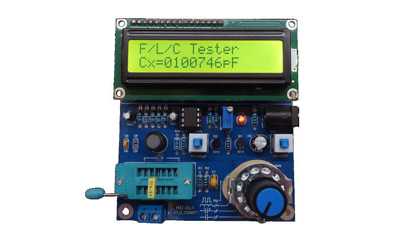
The HU-053 kit consists of a double-sided PCB, a bag of components, a transparent acrylic enclosure, plus all the nuts and bolts required for assembly. The result is a small device measuring 91 × 106 mm with a height of 28 mm. The most recognizable components are an alphanumeric LCD, a large 40-pin STC89C52RC microcontroller, a three-pole, four-position (3P4T) function selection switch for, and a ZIF socket for connecting the component to be tested. The unit is powered by a 5-V supply.
In this second installment of our Reverse Project series, Elektor engineer JFS takes the HU-053 LC-Meter apart and looks at ways of improving it. As it turns out, this is not too complicated. Download the article below to find out what can be done to turn a cheap kit into a usable measurement instrument.
The HU-053 kit consists of a double-sided PCB, a bag of components, a transparent acrylic enclosure, plus all the nuts and bolts required for assembly. The result is a small device measuring 91 × 106 mm with a height of 28 mm. The most recognizable components are an alphanumeric LCD, a large 40-pin STC89C52RC microcontroller, a three-pole, four-position (3P4T) function selection switch for, and a ZIF socket for connecting the component to be tested. The unit is powered by a 5-V supply.
Improving the LC-Meter
After assembling the device and trying it out, we quickly noticed that the accuracy of the meter was about as low as its price. Excellent! Now we had something to set our teeth in…In this second installment of our Reverse Project series, Elektor engineer JFS takes the HU-053 LC-Meter apart and looks at ways of improving it. As it turns out, this is not too complicated. Download the article below to find out what can be done to turn a cheap kit into a usable measurement instrument.
Reverse Project, a Series of Free Projects by Elektor
This article is the second of a hopefully long series entitled “Reverse Project” about hacking and modding kits, a new initiative that is exclusively available to our e-zine readers. Enjoy! Subscribe
Tag alert: Subscribe to the tag Reverse Projects and you will receive an e-mail as soon as a new item about it is published on our website! Read full article
Hide full article


Discussion (3 comments)
robral 7 months ago
Nice to have the Product Manual from Manufacturer as it has a couple of useful operating instructions. Thanks to Google Translate since I don’t read Chinese.
The product manual does mention that the C5, C6 capacitors will give errors but downplays their significance: Page 36: “Because the capacitance C5 and C6 on the circuit board have errors with the actual capacitance, and the measured capacitance is also wrong with the actual standard value, the measurement error may be slightly larger.”
As recommended by Jean-François Simon, I replaced C5 and C6 with 1nF dipped mica ±5% which I had from a Cornell Dubiller Electronics Kit6. Both measured 1.04 nF on an LCR45 meter (but which has not been calibrated in more than a year).
I believe almost any electronic device needs time to warm up and stabilize; the manual recommends it: Page 35: “The device is in the preheating phase within one or two minutes after the device is powered on.”
Once or twice the unit seemed to be “frozen” and would not measure a non-polar cap. A power cycle and recalibration worked.
I measured many non-polar caps, electrolytic and tantalum caps, inductors, and frequencies with the HU-053, my LCR45 and my Keysight U1273A multimeter, with fairly matching results. Measurements always seemed more “jumpy” on the HU-053.
Minor complaints: the finished board did not fit exactly on the 4 mounting screws but could be “worked” on. To measure polar caps you made need to adjust the voltage to 3.16 volts on U2. But there are no test lead access holes on the cover. Since I live in the U.S. my shipping cost was almost as much as the kit itself. Nevertheless, I’m glad I bought and built it.
robral 7 months ago
I drilled a couple of holes. Now I can insert E-Z Hooks to attach to pins 4 and 5, with power off. Then it is easy to measure that voltage and adjust it.
J.F. Simon, Elektor 7 months ago