

10Km SubGHz RadioTransceiver with Energy Harvesting Power Supply
A wireless sensor networks(WSN) and Ιnternet of Τhinks(IoT) probe.
Yes it's true. The communication between transmitter and receiver is absolutely stable at more than 10 Km (line of sight) distances. And all this with just 10dBm output from the internal (single chip processor and RF radio) power amplifier.
The project is based on two amazing chips from Analog Devices .The ADP5090 and ADuCRF101 has been designed to used on autonomous systems(remote data collection and then wireless transmission of these data).
The ADP5090 is an integrated boost regulator that converts dc power from PV cells or TEGs. The device charges storage elements such as rechargeable Li-Ion batteries, thin film batteries, super capacitors, and conventional capacitors, and powers up small electronic devices and battery-free systems. The ADP5090 provides efficient conversion of the harvested limited power from a 16 μW to 200 mW.
The ADuCRF101 is a fully integrated single chip data acquisition solution designed for low power wireless applications. It features a 12-bit ADC, a low power Cortex™-M3 processor from ARM®, a 431 MHz to 464 MHz and 862 MHz to 928 MHz RF transceiver, and Flash/EE memory packaged in a 9 mm × 9 mm LFCSP.
I have designed two cards based on these chips.
The first pcb is an energy harvesting power supply. I use a 2V solar panel with 60ma peak output. The photovoltaic panel charging a 3,7V 700mAh Li-ion battery. The output from the solar panel and the battery drives a ADP190 (linear voltage regulator) which finally gives us 3.3V stable output.
The second pcb is designed around ADuCRF101. This card can be supplied with energy from the first card(ADP5090 pcb). So totally we can have an energy-autonomous system. It has been manufactured so that it is possible for us to experiment with the power amplifier of the RF transmitter (Single-ended or differential PA configuration). The card can work either as a receiver or as transmitter or as a transceiver. The loaded firmware could make the difference.
Currently I have built two code files.
The 'Transmitter code' firmware converts the card into a transmitter who continuously emits the message "hello world". One message a second. The on board red led lights up after each transmission.
The 'Receiver code' firmware converts the card into a receiver who constantly listens the air for a message. The on board red led lights up after each successfully message reception(CRC correct).
I use these cards to measure the maximum transmission distance.
To download the code into the cards you have to use the jtag adapter from the 150210 ELEKTOR project.
These two cards can be used as a starting point for many experiments and applications around the autonomous wireless transmission systems.
Have a nice experimentation.
Updates from the author
Gerasimos.Theodorou 7 years ago
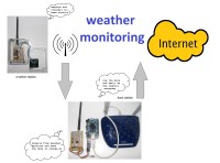
With this design I want to test the weather station under real outdoor conditions. The station should be energy-autonomous through the photovoltaic, the battery should last for years, the housing should withstand the high solar radiation, humidity and rain.
Weather station
A analog temperature sensor chip TMP36 a voltage divider and a ADG701 switch have added compared to the previous design. Also the pcb has been placed in a waterproof box. Currently the weather station measure the voltage of the Li-ion battery and the temperature.
The source code of the weather station are attached. The station's code flow is very simple. The station is generally in sleeping (hibernate) mode. Every 10 minutes wakes up, takes measurements, transmit the measurements and goes back to sleep. The station does not wait for acknowledgement from the base station.
The size of the transmitted packet is 20 bytes. The station do the conversion of measurement data into printable ASCII format. The transmition frequency is 915MHz, the output power 10dbm and the speed 1Kbps. These values guarantee line of sight transmission range greater than 10Km. Transmission power, transmission frequency and transmission speed can be changed very easily with minor changes to the source code.
The weather station power consumption is very low. In hibernate mode the total consumption is only 3μA. In this situation, the 700mAh Li-ion battery could power the station for about 26 years without recharging from photovoltaic. In transition mode the consumption is approximately 32mA. With 10 minute transmission interval the average power consumption is only about 20μA and the battery is able to power the device for 4 years without recharging. The wather station power consumption may drop much more if reduce the transmit power or increase the transmission speed. This also will reduce the maximum transition range.
Base station.
On the other side there is the base station. The base station is continuously in reception mode in the frequency that the weather station is broadcasting waiting for information packets. The base station never falls into sleep but always sniffing the air for packets. After receiving a packet, it advances it to the serial port and returns to receiving mode.
The base station power consumption is approximately 12mA. The base station is powered by orange pi from the USB to RS232 converter.
Orange pi pc or raspberry.
This device is responsible to organize the weather station packets into log files and also to email me the log files.
The serial port of the base station is connected via USB to RS232 converter (CP2102, CP2104 or similar) with an orange pi pc running armbian. A raspberry pi could be used. Orange pi was chosen because it is much cheaper.
Each day a logfile is created. The name of the logfile is the date of current day. Each information packet along with the time that the package came to base station, is placed in a row of the logfile. At the end of the day the logfile is sent to our email and then the logfile of the new day is created. No programming language was used but all the work is done by a bash script the weatherscript which is attached.
WeatherStation code (823kb)
WeatherStation schematics 1 (226kb)
WeatherStation schematics 2 (124kb)
BaseStation schematics (220kb)
Bash script (50kb)
athens 01072017 temperature measurements (40kb)
base-station.JPG (1246kb)
orange-pi.JPG (1145kb)
weather-station.JPG (865kb)
image4.jpg (1870kb)
Gerasimos.Theodorou 8 years ago
Currently I have downloaded the ADRadioNet's code on both cards that I have built. The first card has been assigned as "center point" and the second as "end point". I have not built third card to try the "router" option. Also currently has not been added sensors on the "end point" card.
Using a cheap usb to serial adaptor (CP2102 or similar) and the ADWSN-UI-Tool I can see the whole operation of the network. The full free source code and a network tool are provided by the site of analog devices (http://sdk.analog.com/dw/sdks.aspx?file=ADRNT-01-2.0.1). Analog devices requires a simple registration before they get you the permission to download the files.
Also I have attached a simple guide about the ADRadioNet and a user manual of analog devices network tools. Attention. There is no need you to buy the evaluation boards from analog devices. The cards that I have construct can replace the cards from analog devices.
With this adaptor we can download the firmware and connect the boards with analog devices' tool (1617kb)
adradionet-configuration-tool-1upd.gif (478kb)
adradionet-configuration-tool-1upd.gif (478kb)