

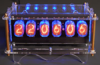
6-digit Nixie clock [150189, 180588]
This is a remake of the Simple Nixieclock (140013-1). After this project was published we got a lot of questions from our readers about changing the time zone, which was fixed to GMT+1 in the original design but could be altered in the source code of the PIC microcontroller.
Update March 6, 2025
Due to a software issue concerning automatic daylight saving time (DST), the clock started showing zeroes at the beginning of January 2025. This is because the clock's DST database ends at 2025. Several fixes have been proposed in the comments below. To hopefully solve this issue for once and for all, new software was written that does not try to be clever. DST is manual only. Furthermore, it is open-source plain C without funky libraries, so it should be easy to correct and adapt. It is available in the download section below, under the Software tab.
Developed with MPlab-X IDE v6.20 with free C compiler XC8 v3.0.0. A HEX file is included too.
This project should also be easy to adapt for the 4-digit version of this clock (140013-1, see this project).
Rant
Please remember the Y2K bug. If you weren't born yet, look it up. Don't create software that will stop working 30 or more years from now because you implemented some clever function, and you didn't expect the software to last for so long. Please, please, always try to make your work future-proof.
Usage
The new software is simply clock software. It shows the time and that's it. No clever features, no alarms, just the time. If I didn't make dumb mistakes, with this software, the clock will work as long as the GPS will work (and even beyond but with less precision).
Daylight Saving Time (DST, +1 hour) is manual, activate or deactivate it by pressing S1.
When the clock is switched on, it will first test all the digits, then show the time zone (as minutes, 0 to 37) and if “+1-hour” DST mode is activated or not (as seconds, 1 or 0). It can take a long time before the GPS resynchronizes, but you probably have a good spot for the clock with a clear view of the sky. If the GPS drops out, the clock will continue on its internal clock. When the GPS comes back, the clock resynchronizes.
The LED shows if the GPS string has a valid year (i.e. >= 2025, this will work until 2100 because the RMC string does not include the '20' of 2025 [WTF]). When it does, the GPS is outputting stable time data. The time can be good, even if the year is still wrong. Anyway, it is not used by the software other than for showing status information.
The left neon light flashes for every successfully decoded GPS string (RMC). If GPS reception is good, it should flash every second (can vary). The right neon light flashes once per second of the internal clock (stable). The two neon lights are not synchronized.
Keeping S1 pressed while switching on the clock allows setting the time zone (0 to 37; default is 15: GMT+0). Press S1 repeatedly to do so. The value is stored in EEPROM. When S1 is not pressed for 10 seconds, the clock will enter clock mode.
Pressing S1 while the clock is running toggles between +1 hour (DST) or +0 hour (not DST). The value is stored in EEPROM. Default is off.
JP1 selects display of leading hour zero or not.
Original Project Starts Here
This is a remake of the Simple Nixieclock (140013-1, see this project). After this project was published we got a lot of questions from our readers about changing the time zone, which was fixed to GMT+1 in the original design but could be altered in the source code of the PIC microcontroller. The author finally changed the firmware to set the time zone using a switch after reset.
We mentioned in the article that seconds were also counted but not displayed (after all: there were only four digits) and some readers were wondering if the design could be changed to show seconds as well. The PIC18F2480 doesn’t have enough I/O-pins for two extra digits and is replaced by a 40-pin DIP 18F4420. Apart from the two extra 74141’s, Nixie tubes plus an extra neon bulb for separating minutes and seconds digits, there are hardly any changes in the schematic, but of course the PCB layout needed to be redesigned. In the old design we used Russian IN-14 Nixies, but apparently even Ebay-shops in Eastern Europe are running out of stock. The prices have increased dramatically, making these tubes less suitable for new projects. We discussed this with Jan Wuesten, owner of the German tube-webshop www.fragjanzuerst.de (i.e. Ask Jan First), and decided to use IN-12 nixies in this design, which are pin compatible with other oval shaped nixie tubes like the ZM1100 and CD56. Since these are top view nixies, we made a separate PCB for the display that can be mounted perpendicular to another PCB containing the rest of the hardware. Six 10-way (box) headers (spaced on a 100mil grid) are used for the connection between the two boards, making it relatively easy to make your own display on vero board if you want to use other types of nixie tubes.
Discussion (81 comments)

Leonard Scheepsma 3 weeks ago
Like all 6digit clocks discussed here, mine stopped working as well due to the DST issue, and is in need of PIC reprogramming. Personally, I am not able to do this (zero knowledge on this topic, and no equipment available to reprogram).
Is there someone in this forum, preferably in the Netherlands, able to do this for me? No need to do it for free, a reasonable cost compensation is certainly agreeable.
Thanks in advance, Leonard
email: tubes.leonard@hetnet.nl

esnap 1 month ago
Regards Ernest

Geert Michiels 2 weeks ago

Michael Moser 1 month ago
My first steps were thus to install the latest version of the Microchip IDE (v6.25) and then to dig out the - I think - latest available version of the SW ("180588-027-05-ORIGINAL-Version 4.7").
I then imported the project into the IDE. That worked.
Next - before making any changes - I was trying to rebuild or "make" the original SW.
However, when I am compiling the project it ends in the following error:
...
In file included from Interrupts.c:10:
In file included from ./Interrupts.h:11:
./GenericTypeDefs.h:53:9: error: unknown type name 'bit'
   53 | typedef bit                 BIT; /*bit is an additioanl implementation in XC8 */
...
Could some kind soul elaborate what this error means? Apparently the version when this SW was originally developed was v4.x. Is "BIT" a type that was available only in an earlier version of the IDE or what does this error mean? Where is that type "BIT" supposed to come from?
(While I do have an IT background I am completely new to the MPLAB X environment. So bear with me. Or - alternatively - is there some description how to prepare and setup the environment to build that project?)
ElektorLabs 1 month ago
FYI; a brand-new MPLAB-X project is available in the download section with 100% fresh code and without automatic DST. You can use it as a starting point for adding features.
In theory, the most recent software is on this page, ideally in the Download section, under the software tab. Where did you find that file "180588-027-05-ORIGINAL-Version 4.7"? Is this Andy's software? I believe that is a cloud MPLAB-Xpress project, not MPLAB-X and it doesn't compile in MPLAB-X.

fminne 1 month ago
So, I have made a new HEX-file, which tackles this concern. I have calculated and implemented the Daylight-Saving Timetable until the year 2124. So, I am quite convinced that no one that has built this Nixie-clock will outlive this table.
But what after 2124? No problem, as the firmware of the Nixie-clock only looks at the 2 last digits of the year, in 2125 it will use the Daylight-Saving Time start and stop date of 2025. That means that the clock may be wrong to max. 7 days to switch automatically between the summertime and the wintertime. So, the problem of 0:00:00 will never occurs anymore, even not after 2124. And to be honest, I don’t think that Daylight-Saving Time will still be in use in 2125. In the case that Daylight-Saving Time will not be used anymore, you simply must switch of the automatic update between summertime and wintertime, by powering the Nixie-clock on and manipulating the switch to set the correct settings in the EEPROM. The Leap-Years table was also modified, and yes, 2100 is NOT a leap year. One big remark about this firmware, it takes a lot of time to synchronize the Nixie-clock with the GPS-clock. It took my Nixie-clock more than 2 hours before the correct time was displayed. I live in GMT+1-zone, but after I installed the new firmware, the Nixie-clock displayed the GMT+2-time. Only after more than 2 hours, the clock suddenly displayed the requested GMT+1-time. So please be patient with the Nixie-clock after applying the new firmware. I hope everyone will be pleased with the new version of the original firmware, taking the Nixie-clock accurate until 2124 (and further). Kind regards, Frank.
ElektorLabs 1 month ago
Daylight Saving Time (DST, +1 hour) is manual, activate or deactivate it by pressing S1.
When the clock is switched on, it will first test all the digits, then show the time zone (as minutes, 0 to 37) and if “+1-hour” DST mode is activated or not (as seconds, 1 or 0). It can take a long time before the GPS resynchronizes, but you probably have a good spot for the clock with a clear view of the sky. If the GPS drops out, the clock will continue on its internal clock. When the GPS comes back, the clock resynchronizes.
The LED shows if the GPS string has a valid year (i.e. >= 2025, this will work until 2100). When it does, the GPS is outputting stable time data. The time can be good, even if the year is still wrong. Anyway, it is not used by the software other than for showing status information.
The left neon light flashes for every successfully decoded GPS string (RMC). If GPS reception is good, it should flash every second (can vary). The right neon light flashes once per second of the internal clock (stable). The two neon lights are not synchronized.
Keeping S1 pressed while switching on the clock allows setting the time zone (0 to 37; default is 15: GMT+0). Press S1 repeatedly to do so. The value is stored in EEPROM. When S1 is not pressed for 10 seconds, the clock will enter clock mode.
Pressing S1 while the clock is running toggles between +1 hour (DST) or +0 hour (not DST). The value is stored in EEPROM. Default is off.
JP1 selects display of leading hour zero or not.
The software is an MPLab-X project (not cloud based) compiled with XC8 v3.0.0. A HEX file is included. It is plain self-contained C (except for the __delay_ms() function, which is XC8) with fuse settings, etc. It should be quite easy to adapt this software for the 4-digit Nixie clock that preceded this 6-digit version (but I don't have one). This is a complete rewrite from scratch, no old code.
Enjoy & improve if needed.
Geert Michiels 1 month ago
I have a bunch of the 4 digits "https://www.elektormagazine.com/labs/simple-nixieclock-140013-i" clocks that have same issue. Can we kindly have a simular fix for these?
esnap 1 month ago
I just rewrote the 140013 program in MPLAB XC8 C for my own PIC18F26K22. That works fine. The DST problem is solved and will change time automatically at the start and and of the DST period. I am willing to make the program suitable for the original PIC18F2480 when enough people are interested. I will have to buy the chip in order to test the program before I make it available and upload it here.
Regards Ernest

Greg77 2 months ago
the nixie clock was a project of my father who made a lot of these clocks for family and friends purpose.
He died in 2021. It was a shock for me to see the clock on January 1st 2025 to be "broken".
Thanks to this forum I bought the programmer I flashed the new firmware onto the PIC18F4420.
Clock works now again until 2032.
You can imagine the importance for me personally...
I am able to program only PIC18F4420 with firmware provided here (at least it worked for me).
I offer programming this PIC for you for someone it is to technically for.
Hereby it would be so nice if someone could prolong the date of firmware from 2032 until 2050 or so working (entering different daylight saving times is the problem).
What I need is only the PIC chip, not the whole clock !
Extract it and send it to me safely (something like sticking chip in polystyrene).
All I want is shipping cost for returning chip to you.
My location is in Germany.
No warranty. I will try to fix your clock.
Contact me under for further details:
nixieclock@superbrain.network

Jean Racine 2 months ago
J'ai assemblé 2 kits 6-digit Nixie Clock et je me suis aperçu qu'elles affichent l'heure de façon alternative entre 00.00.00 et une heure décalée d'environ 30 secondes..... depuis le 1er janvier 2025
Il semble que se soit un problème logiciel installé dans le PIC.
Où puis-je obtenir 2 exemplaires de ce PIC (IC 4) avec le programme corrigé ?
Merci de votre réponse
Jeanjean.racine@wanadoo.fr

Tim - 2 months ago
Thanks for the great work keeping the nixie clocks up and running!
I have the 4 digit version: https://www.elektormagazine.com/labs/simple-nixieclock-140013-i
I saw that this design uses a different microcontroller, does anybody know if it's feasible to update firmware for the 4 digit version? I do not have the tools and skills to do so.
Any help would be greatly appreciated!
Best regards,
Tim
Greg77 3 months ago
Since Jan 1th 2025 a lot of clocks does not funciton anymore. 0:00 failure
Is there any possibility for a firmware with indefinite time of use ?
After fixing now, you can use current firmware until end of 2032 luckily.
Thanks the developer for that !
But indefinite would be far better.
And if someone want prgramming of the PIC chip. Please let me know. I will do it for you.


fminne 3 months ago
But I don't know how that can be done as one of the issues is that no one knows how long we will still use daylight saving time. Perhaps it will be decided to stop all that daylight saving time this year. Who knows.
The major issue, according to me, that it is not possible to make it indefinite, is the daylight saving start time and stop time changes each year. So that exact moment has to be introduced in a database in the firmware for each year (that is what I did for the years until 2032).
But, on the other hand, it is always possible that your clock becomes indefinite, when you do the setup of disabling the daylight saving time, and to manually change 2 times a year your time-zone so that the clock is again at the actual right time. Not very handy, but possible.
Kind regards, Frank.

RedTopcat 3 months ago
is it possible to provide documentation explaining the structure of the following variables?
NORM_YEAR:
LEAP_YEAR:
LIMITS_TABLE:
Many thanks to Frank for the finished code, but I would also like to understand what has been changed.
Thank you very much
fminne 3 months ago
NORM_YEAR: Januari start at 00 hours.
Februari starts at H'02E8 (744 hours) (31 days x 24 hours =770)
...
LEAP_YEAR: same as NORM_YEAR: , but Februari has 29 days, so March starts 24 hours later.
LIMITS_TABLE: first byte indicates the year (H'24 is indeed 2024). That was the last year that was defined.
The second and third byte is the start time of the day light saving time, the third and the fourth byte is the stop time of the day light saving time.
I added those "dates" in " LIMITS_TABLE:" until 2032.
Kind regards, Frank.


hwfaber 3 months ago

toolak 3 months ago
The 2014 article said :
" The microcontroller software is designed to be able to control clocks with seconds display (six digits) as well. Although the present design has only four digits, the entire software is described here."
So I tried to program the PIC18F2780 tru PICkit3, MPLA_IDE (not the full stuff MPLAB_X, with Andy Leitch PIC18F4420_NoMods_4.5.hex software, on the circuit.via K1.
And ... It's perfectly working : with date display sometimes and anti-poisoning circus ;).
Regards,


elRetro 3 months ago
some questions about how the HEX file gets onto the chip:
Does the clock have to be on or off to write?
What has to be considered with "fuses", what has to be set?
The PIC18F4420 has been recognised, what happens now?
Many thanks for the HEX file!
fminne 3 months ago
I powered up my clock after the PICkit3 was connected. Then I first read the content of the original firmware and saved that to a file. That stap is not really necessary, but I wanted to be sure that I could go back.
Then I flashed the PIC18F4420 with the tool. Afterwards you can also do a verify.
After shutting down the clock again, I disconnected the PICkit3. Now everything should be OK.
Concerning the fuses: they are already blown the first time, so that is OK. I didn' bother about them in any case and my Nixie-clock is working correctly.
Good luck, Frank.

F1Andy 3 months ago
Mine runs out in 2029, so it is a good reminder to update.
I will post code that runs to 2050 in the next week or two.
It also has a small change to accept data from GLONASS modules.
(I have been thinking of an everlasting code version, but haven't had time to do it - it needs a fundamental re-write of the code to make the algorithm work.)
fminne 3 months ago
First of all, this only applies to Nixie clocks using the original PIC firmware. So Nixie clocks using Andy's firmware are not affected.
There are 2 solutions, in my opinion:
- the simplest correction, where you don't need any tools, is to disable automatic daylight saving time. You do this with the switch: turn off the Nixie clock. When you turn it back on, you have to move the switch S1 in less than 5 seconds. The leftmost Nixie now indicates the setting of automatic daylight saving time. When it is set to “1,” you must turn the switch and the value will become “0”. Now automatic daylight saving is turned off. When the leftmost Nixie flashes, you must manipulate the switch again. Now the 2 Nixie tubes of the minutes are going to display the value between 0 and 37. That is the time zone you are in. So you have to set those so that the time is correct for you. After a few seconds of not changing S1, the value is stored in the EEPROM. You will now have to adjust this "timezone" yourself every time it switches between daylight saving.
- and now the 2nd possibility: reprogramming the PIC18F4420. For this you need the necessary tools. The “error” actually lies in the firmware. The daylight saving time was defined until 2024. Since we are now 2025, the clock does not know what to do with this and everything crashes. Leap years were also defined only up to 2024. I added both leap-years and daylight saving periods until 2032 and created a new HEX file for this.
Until today, I didn’t have any experience with programming a PIC. I have learned a lot today! My Nixie-clock is back into business until the beginning of 2033!
Good luck with it, Frank.


Rolf Hase 3 months ago
auch bei mir wechselt die Anzeige alle 3 sec zwischen Uhrzeit und 0. Wobei die Uhr eine Stunde vorgeht und nicht sekundengenau ist, d.h. nicht vom GPS stammt. Das Problem trifft mich besonders hart, da ich viel Arbeit in eine Erweiterung unterhalb der Nixieröhren mit einer LED-Matrix für die Temperaturen und Datum mit Wochentag gesteckt habe (s. Bild). Mit den Pics hatte ich nur am Rande zu tun, daher meine Bitte an den Autor oder an Leute, die sich auskennen: Eine neue Software muß her, möglichst mit dem preiswerten GPS-Modul Neo-6M, da geht nämlich TTL-Kopplung. Wenn das alte Modul noch geht ist es natürlich auch gut. Wie der Arduino-Mensch den Pic programmieren soll, muß natürlich auch beschrieben werden. Möglichst mit einem Arduino als Programmiergerät und einer Mini-Ide, wie beim Bootlader brennen. Wenn es geht, kein Neukauf!

Arduino47 3 months ago
Here is the firmware correction axis for the most knowledgeable:
Solution 1:
The author should use a generic logic to detect leap years dynamically:
CALC_LEAP: MOVLW 0x04 ; Check if the year is divisible by 4
MOVFF YEAR_BCD, WREG ANDLW 0x03 ; Mask to check the 2 least significant bits
BTFSC STATUS, Z ; If zero, leap year
GOTO ITS_LEAP
GOTO NON_LEAP
This will avoid manually adding each leap year.
Solution 2.:
Extend the data tables LEAP_YEAR, NORM_YEAR, and LIMITS_TABLE do not contain data for years after 2024, add corresponding entries for future years.
For example: LEAP_YEAR: DB 0x2028, 0x2032, 0x2036, ... NORM_YEAR: DB 0x2025, 0x2026, 0x2027, ... ! Happy New Year !!
Arduino47
fminne 3 months ago
To be clear, I am a total dummy in this PIC-programming, so I need some help.
In the original Nixie_OCC_4220_Elek_V2.asm-file, I see the following tables defined:
NORM_YEAR: DB 0X01,0X00,0X00,0X02,0X02,0XE8,0X03,0X05,0X88,0X00,0X00,0X00
DB 0X04,0X08,0X70,0X05,0X0B,0X40,0X06,0X0E,0X28,0X00,0X00,0X00
DB 0X07,0X10,0XF8,0X08,0X13,0XE0,0X09,0X16,0XC8,0X00,0X00,0X00
DB 0X10,0X19,0X98,0X11,0X1C,0X80,0X12,0X1F,0X50,0X00,0X00,0X00
LEAP_YEAR: DB 0X01,0X00,0X00,0X02,0X02,0XE8,0X03,0X05,0XA0,0X00,0X00,0X00
DB 0X04,0X08,0X88,0X05,0X0B,0X58,0X06,0X0E,0X40,0X00,0X00,0X00
DB 0X07,0X11,0X10,0X08,0X13,0XF8,0X09,0X16,0XE0,0X00,0X00,0X00
DB 0X10,0X19,0XB0,0X11,0X1C,0X98,0X12,0X1F,0X68,0X00,0X00,0X00
I really do not see how this HEX-data is transferred to 2012, 2016, 2020 and 2024 (for the LEAP_YEAR) and, I presume 2013, 2014, 2015, 2017, 2018, 2019, 2021, 2022 and 2023 (for the NORM_YEAR).
So I really do not know how this table must be edited to get the years 2025 .. 2037 in them.
Can you perhaps help me with how these tables are build?
Thank you for your help, Frank.
fminne 3 months ago
I believe that the original firmware was written by @Lucky.
So the question is if @Lucky is aware of this bug, and if he is willing to investigate it. I personally believe that the issue is due to 2025 not being available in the DTS-tables of the firmware, and that the PIC does not know what to do with 2025 in the date-train of the GPS.
@Andy already proposed to check the firmware (big thanks to @Andy). Perhaps he is able to modify the firmware of @Lucky, so that the DST-tables start now from 2025.
So I think we have to wait to a reaction from @Andy or @Lucky to receive a new firmware. This means that people who wants to get rid of this 0:00:00-isuue will have to reprogram the PIC, and thus will have to have a PICkit3 or higher to do so (I already bought mine yesterday and it will arrive on Saturday).
Kind regards, Frank.

EN0094833ID 3 months ago
Thanks


NickT 3 months ago
Needless to say, I can no longer find any anywhere except a dodgy looking example for £50 on the usual market place. I’ve changed the caps around the 3v3 supply, reseated the uP, remade the solder joints around the GPS but to no avail.
It occurs to me that the GPS unit is probably sending a NMEA word that is “telling” the up uP what the time is, so it should be possible to use another module to do the same. I wondered if anyone else had tried to do anything similar, or has seen the same fault ?
Nick

THIRION Gerard 3 months ago
Idem pour moi, l'affichage alterne toutes les 4s l'heure et 00.00.00
la led clignote anormalement
Ancien PCB non modifié issu des 1ers kits d'Elektor
J'espere qu'Andy trouvera une solution rapidement
Mail perso :dubi@cegetel.net
Bonne année 2025 a tous
Arduino47 3 months ago
Le code semble vérifier explicitement certaines années (2012, 2016, 2020, 2024) pour déterminer si elles sont bisextiles, mais ne gère pas correctement les années au-delà de 2024.
Solution 1 : L'auteur devrait utiliser une logique générique pour détecter les années bisextiles dynamiquement :
CALC_LEAP: MOVLW 0x04 ; Vérifier si l'année est divisible par 4
MOVFF YEAR_BCD, WREG
ANDLW 0x03 ; Masque pour vérifier les 2 bits de poids faible
BTFSC STATUS, Z ; Si zéro, année bisextile
GOTO ITS_LEAP
GOTO NON_LEAP
Cela évitera d'ajouter manuellement chaque année bisextile.
Solution 2. Étendre les tables des données
LEAP_YEAR, NORM_YEAR, et LIMITS_TABLE ne contiennent pas les données pour les années après 2024, ajoutez des entrées correspondantes pour les années futures. Par exemple :
LEAP_YEAR:
DB 0x2028, 0x2032, 0x2036, ...
NORM_YEAR:
DB 0x2025, 0x2026, 0x2027, ...
Ce n'est peut-être pas le bon axe... mais à vous de voir !
Bonne année !!
Arduino47
EN::
Hello, even if it is not my subject, out of curiosity, I quickly visited the code to try to lead you to the problem, you have to review the Calculation of leap years.
The code seems to explicitly check certain years (2012, 2016, 2020, 2024) to determine if they are leap years, but does not correctly handle years beyond 2024.
fminne 3 months ago
The LED 1 shows that there are problems with the GPS-time. Normally it should blink each second. But that is not the case. Each time it does not receive a good time-string from the module for 4 seconds, the display shows 0:00:00.
I don't know what the cause is. Is the GPS-module only working correctly until 2024? Or what is going wrong?
I hope that Andy will be able to help us.
Kind regards, Frank.


KlausF 5 months ago
ZM1100, ZM1102, ZM1162A, ZM1180, ZM1182, ZM1186, ZM1188, CD43,
ATTENTION ! Only 11 or 12 pin versions are suitable !
Best regards, Klaus

DE0082104ID 11 months ago
i bought the kit in 2017 or 2018. A short time after that, i had a heart attack and forgot about it, until just recently found the box again.
I am no electronics expert whatsoever, but sucsessfully soldered various kits.
So, to the best of my knowledge and all of the infos about the clock i could find on the internet, i carefully built the kit (mainboard V1.4). Unfortunately it doesn't work as it shoud.
After powering it on, all the 6 tubes light up, but only show the number zero. The neon lamps do not blink. But the red LED flashes fast 5 times or so, stays on, after some seconds flashes once. After a while this repeats.
I checked the solder joints and polarity of the parts and have the 170 Volts and 5 Volts.
Has anyone an idea what i can try to get it working?
Thanks in advance & best wishes from the Black Forest in Germany,
Karlheinz


Bastian Reul 3 years ago
we've bought this Project a few Years ago, and we soldered all together in the last Days. We bought the PCB Version 1.4, but had to change the GPS Sensor to the A2235 (G403) and we installed the Software Version 4.5. (Without any modifications) The GPS Module sends continuously String to the PIC, but the Nixies shows only the Baudrate 4800 and later 9600. The Clock is placed directly by a big Window, so it has a nice clear view to the Sky. What are we doing wrong?
We are thankfully for any tips or suggestions.
Kindly regards,
Bastian

Axiris 3 years ago
F1Andy 3 years ago
When the display shows 4800 / 9600 it is searching for a valid NMEA string starting "$GPRMC....." from the GPS receiver module.
The GPS module always sends data when powered. This does not depend on the satellites.
So the issue is with the connection from the GPS module to the PIC. Check for shorts, dry joint (GPS module is tricky!) , pin bent under the PIC. ( I think - but not certain - that there is also a pull up resistor to the GPS to put it into serial mode - check that is connected too.)
The software listens first at 4800, then at 9600, then back to 4800, etc. This allows you to use an inexpensive GPS module on a cable from a car dash-cam (they come with a 3.5mm 'headphone' connector.)
Attached is version 4.8:
4.6: Anti-Poison "one-arm-bandit" -fixed numbers all same instead of random.
4.7: Last year the DST was a day out (D'oh!) so I updated and also extended the number of years in the look-up table. ADDED: Colour by value as one of the colour choices, so each digit can have its own colour.
4.8 Added decode of strings starting with "$GNRMC" as well as "$GPRMC" so glonass GPS modules also work.
The MPLABX project is attached. Edit the file "copy.bat" to a useful folder to save the .hex files, other wise it will give an error. Needs XC8 compiler.
(The .hex files are attached as well - I just built them fresh, but haven't access to clock to test them. Choose the .hex to match processor type you have, and the Microchip IPE program to flash in the file. )
Best regards,
Andy

DF1VN 5 months ago
I try to understand your comprehensive software, thanks for sharing it!
In your code I found the pre-compiler instruction
#pragma interrupt_level 2
used in front of some functions. If I am correct, this shows to the compiler that the following function will be executed as ISR (in this case as highest priority according to the activated interrupt sources). I understood, that the compiler can accept only one ISR being declared in a program... But I saw several such declarations. From where does the compiler know, which to execute? Or is there another idea behind? Any information to understand your concept will be appreciated.
Thank you much!
Best regards,
Andreas
ElektorLabs 3 years ago
Best regards,
Luc
F1Andy 3 years ago
The two things on my list are:
1) Add a feature to reverse the colours of the back light. The 5mm through hole LEDs on my backlight PCB have a different RGB order to the SMD ones on the Elektor backlight PCB (so, asking for Red shows Green...)
2) Instead of looking up the date and hour of DST / BST in a table, use a calculation so the software never expires. Last version DST automatic mode ends in 2032..
Also, it would be nice to have a "trimming" function to adjust up to +/- 3 seconds to match the real time exactly, but that needs a lot of work to do.
I have the VFD clock kit, and plan to port the software over, to have give it the same features.
I just need to find the time to do these things...!
Related:
I also made an NTP internet time to NMEA GPS data converter with ESP module. Allows Internet time to be used instead of GPS, for when the clock is installed in a position where it can't see the sky. I need to document it though.
Andy

maros336 3 years ago


Marv_M 4 years ago
I recently finished soldering my nixie clock but unfortunately the programming of the ic is not working as you can see on the pictures I uploaded. Furthermore when I connenct the clock to 12V power just one tube glows the digit 7 and a other one just a half three. The diming is working on all tubes
Thank you
F1Andy 4 years ago
The most common issues are with solder bridges/dry joints, pins folded under the ICs when installing, and connectors not fully mated.
Can you take a fresh look at all the solder connections and double check for shorts, and even lift chips out of sockets to check the pins are straight please?
Can you check you have 5V on the board? You can measure at the expansion header.
Can you measure the high voltage? Low voltage would cause a half lit number on a Nixie.
Can you double check the Nixie board it properly connected to the main board. If the connectors aren't all the way in, it will give strange illumination. (The male headers are used in reverse to make the boards fit the case I think?)
The Pickit cannot supply enough power for the whole board . Make sure you don't set 'power from Pickit' in the IPE software's options, and keep the board powered from your supply when programming.
Post back what you find!
Andy
(AFTER posting, my screen refreshed with Luc and Walterh's comments - sorry for any duplication!)
Marv_M 4 years ago
nbproject/Makefile-impl.mk:39: recipe for target '.build-impl' failed
make: *** [.build-impl] Error -1073741819
BUILD FAILED (exit value 2, total time: 1s)
The three LEDs of my pickit are glowing red constantly is that an issue?
F1Andy 4 years ago
Change it to a place you want to copy to, or put REM in front of the line with copy:
REM COPY %INPUT_HEX% %OUTPUT_HEX% /Y
You can find the file in the tree on the left as shown in the attached screen grab.
Andy
Marv_M 4 years ago
How can I change the neon lamps so that they glow all the time and do not blink?
Kind regards Marvin
F1Andy 4 years ago
If you leave the link on, like in the photos, it will reset the EEPROM.
(The intention is that you can reset to a known configuration by holding S1 pressed until a long beep after applying power.)
The Neons blink every time an NMEA string is received and successfully decoded. I will have to look at adding "Neons Blink/Steady" as an option in the software.
Andy

Luc Lemmens 4 years ago
I'm not sure what the programming issue is, the picture of your computer screen reports that there is no connection between the PC and the microcontroller, but the top line is truncated (target circuit may require more..?). If you cannot program IC4, I'm not surprised that the clock doesn't work correctly...
Marv_M 4 years ago
Luc Lemmens 4 years ago
Did you remove the enclosure from the Pickit?

walterh 4 years ago

Richard Leach 4 years ago
the clock is running v 4.7
Axiris 4 years ago
I think it is a software feature to indicate that the time is going to change due to DST being turned on or off.
F1Andy 4 years ago
It calculates that the time has to go back an hour because it is after 2am.
Next time around, the time is 1am so it doesn't need to take the hour off, so bext time it is 2am again...
ping-pong DST on/off every second.
Settles after an hour
One of those things that can be sorted with a bit of code shuffling, but I never got around to doing.
Andy

wolfje01 4 years ago
In de magazine there is a reverence to the new PCB
( in de store 180588-1 V1.1 www.elektor.nl/150189-1 ) However the link is not working, there is a message the page does not exist.
Is it sold out or is it still possible to order the new print?
Regards,
Rick

AG-Energy 4 years ago
I'm also interested in the pcb. But I have no experience to build it or to let it build.
It would be nice, if we plant an interest group to get some pcb. However, we need at least one who has the gerber file and can organise the production of the pcb.
How much would it appr. cost?
Regards
ElektorLabs 4 years ago
Marv_M 4 years ago
Richard Leach 4 years ago
F1Andy 4 years ago
The software receives the strings under a timed interrupt and has no problem keeping up. The string is then decoded, which can take a variable time depending on the maths needed. Only the GPRS string is decoded, others are ignored.
The display is updated with the current time when the next "$GPRS" header is received, as the arrival of the start of the string (when only one string is sent) is very predictable, eliminating jitter.
When several string types are sent, the timing of the transmission by the GPS is no longer consistent.
The original module sends out several different strings by default on power up. Commands are sent to the GPS module to disable the extra messages at power up. (That's why the TX pin of the PIC is connected to the GPS module RX pin).
The PPS signal isn't monitored in the software at present, as it requires a strong signal - the pulses may drop out when the clock is indoors, so it was not useful.
The GPS module free-wheels and generates the time itself if it looses satellite signal; and so continues to send a valid time string. While the GPS module has satellite lock, it will trim its internal oscillator so it will maintain accurate time for a long time. That's why it counts from midnight (plus your timezone) at power up, until satellites are locked.
I will have to try the new module to see what can be done.
Andy

prudencio 4 years ago


netzwerk-manne 4 years ago
Nach langem warten ist nun auch endlich der PIC-Controller mit der neuen Software eingetroffen und ich habe sogleich die alte, funktionierende Nixie-Clock demontiert und gemäß der Dokumentation modifiziert. Eigentlich funktioniert (fast) alles so wie es soll, nur das mit der Modifikation zur Datumsanzeige leider nicht!
Ich habe auf der Display-Platine die untere Leiterbahn des Neonlämpchens getrennt (x-mal nachgemessen). Dann auf der Rückseite die beiden Neon-Lämpchen mit einem Draht verbunden. Zum Schluss die "3" der ganz linken Nixie mit dem mittleren, oberen Stift der Kontaktleiste verbunden. Alles x-Mal überprüft.
Jetzt werden beim Start der Uhr 6 mal die Null angezeigt, aber ganz links blinkt die "3" immer mit, genau wie die Neon-Lämpchen. Zwischen der "3" und den Neon-Lämpchen besteht keine Verbindung.
Mir gehen jetzt so langsam die Ideen aus! Wer kann mir da bitte sehr weiterhelfen und einen Tipp geben?
Beste Grüße
Manfred
F1Andy 4 years ago
Es tut mir leid, dass mein Deutsch nicht sehr gut ist..
Sie müssen Parameter 10 ändern. Dadurch verwendet die Software das linke Neon als "3".
Wenn der Parameter nicht eingestellt ist, versucht die Software das linke Neon zu blinken - aber es ist jetzt mit dem "3" verbunden.
Haben Sie verstanden, wie man Parameter ändert? Falls nicht, kann ich eines kleines Youtube clip machen...
{ Sorry for my poor German. You must change parameter 10 so the software uses the left neon connection as 3, otherwise it continues to blink in time with the right neon. If you have a problem selecting parameters I can make a quick you tube clip.}
Best regards
Andy


Decofast 4 years ago
Another problem is that the parameter seem to be not recording in the eeprom. Everytime I power it on, I have to configure all the parameter again.
Thank you
F1Andy 4 years ago
Sorry to hear you are having problems.
When you say the 3 digit is blinking, do you mean the one on the far left?
If so is it only one Neon blinking?
The parameters are updated to EEPROM when the menu times out and it goes back to show time.
Sounds like you are already navigating the parameters. ( press and release button to show date, press and hold (gets beep) to get parameters list. Then press and release to step through parameter numbers, press and hold to switch between selecting parameter and adjusting parameter. Leave for some seconds to time out...that is when EEPROM should update.
Does it never return to showing time?
BTW: The EEPROM will reset to defaults if the button is held pressed when power is applied - there is a long beep at power up when this happens.
Andy
Decofast 4 years ago
Thanks
Diego
F1Andy 4 years ago
That's very helpful - the display is showing the time before the date is valid.
The expected behaviour is to show the baud rate (4800 for the original GPS) until the current date is received. This makes sure only the correct time for DST is shown.
If the button is pressed during this time, it will immediately show the time and date. Until satellite lock, the date is actually the manufacture date of the GPS, and the time is counts from midnight UTS, so starts counting from 02:00 in Europe.
If the button is pressed when power is applied, it will reset the EEPROM to default.
Can you check that the button is open circuit, and closes when pressed please? If it is a normally closed type that opens when pressed it will behave strangely, and may cause these two symptoms.
Do you get a brief flash of 00 47 00 in the middle digits at the moment of power on? This is the software version in the middle digits.
(The Neons blink each time an NMEA string is received, but time not displayed until date received).
In any case it should not have the flashing digit - I will look into it for you.
Andy
Richard Leach 4 years ago
i.e. make -f makefile
but there are two errors every time, Help would be much appreciated
F1Andy 4 years ago
It will compile with latest XC8 and MPLABX.
Andy
Richard Leach 4 years ago
F1Andy 4 years ago
I created the software in MPLABX, and really recommend you use this to open the project. You can then select the different build version you want from the drop-down at the top.
The project zip file is created by using the "package" function in MPLABX.
Seems this saves all the files needed for MPLABX to open and compile the project, but not for the command line compiler.
Are you able to use the full MPLABX environment?
Andy
(It really is worth using, as it allows you to compile, debug and program in one place).
Richard Leach 4 years ago
I have already tried that and that din't work either. Had another go and got closer errors reported are:
"User defined post-build step: ["C:\Version 4.7"\copy.bat "dist\PIC18F45K22_BothMods\production\Version_4.7.production.hex" PIC18F45K22_BothMods]"
make: Interrupt/Exception caught (code = 0xc0000005, addr = 0x0041C17B)
make: Interrupt/Exception caught (code = 0xc0000005, addr = 0x7755E6D4)
nbproject/Makefile-impl.mk:39: recipe for target '.build-impl' failed
make: *** [.build-impl] Error -1073741819
BUILD FAILED (exit value 2, total time: 4s)
Richard Leach 4 years ago
thanks for the advice
F1Andy 4 years ago
For the benefit of anyone else:
The folder e.g. "Version 4.7" is the project.
Install MPLABX, Install XC8, "Open project" and browse to the folder.
If you get warnings "Resolve DFP...." it means the XC8 version changed and you need just click the warning and select the new DFP.
In the "Projects" window on the left, in Important files, there is a batch file that is called to copy the output .hex file to a convenient folder, which you can edit if desired.
Use the drop down at the top of MPLABX to choose the version..
Andy
Marv_M 4 years ago
F1Andy 4 years ago
-Install Mplabx
-install xc8
-open project
-edit the copy.bat file (found in Important Files in the Project Tree)
-choose latest .dfp if needed (-click on the highlighted links in the error messages if shown)
-choose your version in the dropdown at the top
-build
Andy
F1Andy 4 years ago
Here is the very latest software which adds the option of choosing "By Value" as a background colour.
With this the LED is different colour for each tube according to the number displayed.
The colours are adjusted to go better with this, and the instructions updated to match.
The MPLABX project is attached - it is updated for the latest XC8 compiler.
(There's also a bug fix..)
Modification doc is not changed.

Manolito 4 years ago
Wo kann man den Bausatz kaufen ?
Mfg
Manolito
Axiris 4 years ago
Axiris 4 years ago
AG-Energy 4 years ago
I'm also interessted in the new kit or at least the finished PCB. Hope, you can manage the issues.
Regards,
André
Axiris 4 years ago
For the other components, shipping delays still apply but I should be able to obtain them within a reasonable amount of time.
As for the availability of the PCB, you should contact the Elektor customer service directly.

criki 5 years ago
The use of a shift register (like the 74HC595) with Fet to switch the high voltage could have reduce this number from 60 to 6*3=18 or maybe only 3 if you accept the relations between the 595.
In that cas a smaller microcontroler can be used to do the job and there is no problem to getting 74141 in the future.
F1Andy 5 years ago
80 pin PQFP package (smd 0.8mm pitch leads) maybe a bit difficult to solder though. :-)
http://ww1.microchip.com/downloads/en/DeviceDoc/HV3418-64-Channel-Serial-to-Parallel-Converter-with-High-Voltage-Push-Pull-Outputs-Data-Sheet-DS20005843B.pdf

rudini 5 years ago
Thank you
F1Andy 5 years ago
There is an update that Lucky (It's his project) published on the forum, and I've put a 'C language' program version up too.
It's a great project for hacking.
(Even if you can't get good GPS you can easily modify to:
A) Put an external GPS module (like the ones from eBay for $10 that go into a car sat-nav/dashcam) - you need to program the PIC for different BAUD rate.
B) Use an ESP32 module to fetch time from the web (example in the Elektor ESP32 kit) and send out the serial data as if it were a GPS - easy code, I can give example if you like.)
Andy
ElektorLabs 5 years ago


Nick M 6 years ago
I have checked as many voltages as possible but they all seems to be oke.
Also checked the position of the components.
When starting up the led blinks shortly but stays on the rest of the time, after a minute maybe again a short blink.
The only thing that gave me some doubt was the soldering of the gps module, but i meassured the contacts and seems oke.
someone a solution?

F1Andy 6 years ago
It should be a level shifter from 5V to 3.3V, but I can't see why a transistor is used.
Is this correct:
1) If the PIC outputs 5V: The gate and source of the FET are both at 3V3 so the Fet is off. 5V is blocked. The GPS module's RX pin sees 3V3 because of R19 pull up.
2) If the PIC outputs 0V: The FET drain source are reverse biased so the intrinsic diode in the FET is forward biased pulling the GPS RX pin down to about 0.8V. (The 2N27000 datasheet says the forward voltage drop of the intrinsic diode ranges from 0.88V to 1.5V)
3) R18 has no function: the PIC drives 0V or 5V so is a pull up needed?
I would normally just use a 1.8K resistor in series with a 3.3K resistor to divide the 5V down to a little under 3V3, because the forward voltage drop of a diode can be marginal for logic Low. Am I missing something here?
Thanks in advance.
Andy
(Accidientally posted in the wrong place in this forum yesterday. Moved here!)

emilio1952 5 years ago
I built the clock and it is working very well
I am going to plan to build another one but unfortunately the A2035H module is gone obsolete and, at present, it is very difficult to find
From Maestro datasheets I saw that the A2235H module should be a direct drop in replacement, according them it's enought to pull up the pins 17 and 18 to the 1.8V by 2.2K resistors and make minor alterations to the PCB.
Does anyone tried to do that?
Thanks a lot in advance.

M. Griep 6 years ago
My clock continuously gives a high tone when it is on.
Personally, I only hear it when I listen very closely.
But my children are crazy about it.
Is there a solution for the sound?
F1Andy 6 years ago
This provides a continuous load for the voltage regulator and so keeps it stable.
Andy
F1Andy 6 years ago
I finished my alternative software for the Nixie Clock kit.
It is necessary to change the supplied toggle switch to a push button, in order to access and change the configuration parameters. Other modifications are optional but usefule I think...
The software adds:
- date diplay (EU or USA format) (USA format only unless PCB is modified)
-EU or USA DST correction
-Anti poison display
-Alarm clock function
-WS2812 type LED backlight control
-night time dimming of the backlight
It is ready to handle the next GPS Epoch if needed next year.
Have a look at the youtube clip first to see if it would be suitable for you...
The documents should help to program your clock, but read out the exisiting program first so you can roll back if you don't like it!
(Usual disclaimer of course: I don't take responsibility for any damage caused by using my instructions or software.)
Andy
F1Andy 6 years ago
The NMEA string is updated by the GPS module when signal is lost, so it must be an issue in decoding the string. I have increased the processing speed for handling the received data.
PPS works now, with a short flash of neon when PPS is not detected, longer flash when PPS is synced. I will add an option to revert to 50:50 flashing soon...
Dimming now implemented.
Critically, DST update has another fix, and now updates according to localised time, not GPS time.
I have not tested as much as I would like, so let me know if you find any glitches, or even have feature requests.
By default Nixie dimming is disabled, and USA date format is selected, as this is best for operation without modified PCBs.
Andy

PAUL KINDELL 6 years ago
I have had the updates running for a while now. The one thing I have noticed from the original software is the receiver seems to lose lock more often or at least you are reporting that it has more consistantly. In my basement radio shack the old software always shown locked but the new is out of lock about 50% of the time and that causes the digits to skip.
I look forward to your latest update and will make the 1pps mod as soon as you are ready.
Thanks a bunch for the cool updates!
Paul
F1Andy 6 years ago
I already made some improvements. I have to update the documents and finish testing the code before posting though - but the soon to be released extra features are explained below. (Unfortunately it won't be to the end of October, as I am in Japan for the F1 race)
Continuing in the same philosphy - all the sofware changes are done so that the new version can be run on a clock that only had the toggle switch changed to a momentary push-button. The extra features can be enabled if/when hardware mods are made. This is particulary important if someone is not experienced with soldering - the PPS mod is quite tricky.
HARDWARE:
I have made two more hardware mods-
- Remove crystal and connect Pin 4 of the two decoder chips to the now freed PIC pins.
- Add PPS connection to JP1 - needs and MPSA42 (or any similar NPN) and a 10K resistor.
Photos of the mods are attached - the PPS was a quick test, so excuse the soldering!
This allows dimming the Nixies at night with PWM, since all digits can now be turned off; and truly precise operation of the seconds display.
SOFTWARE
The software has more options now, to enable nixie dimming, and enable the new Auto Dimming feature. (PPS is auto detected).
Auto-dimming from 22:00 until 07:30 has been added, which dims the back light (and nixies if nixie dimming is enabled).
Dimming is over ridden by a long press of the button while time is being displayed; while configuration changes are initiated by a long press when date is being displayed.
Dimming is cancelled when the alarm goes off.
IN PROGRESS:
The PPS mod will allow the seconds to be updated within +/-1mS (due to interrupt latency, and other processing). The PPS pulse is automatically used when present; but the clock simply reverts to show-when-NMEA-received if it is not present. I haven't finished implementing this yet however, but I have tested the signal is arriving into the PIC correctly.
NEXT TO DO:
Add more configuration parameters:
-Setting the start and stop times for auto dimming - we go to bed and get up at different times!
-Configure the backlight colours: This is a personal thing so should be configured like the other options.
PLAN:
I plan to have those all done, tested and documented by the end of October.
-Updated modification list/instructions.
-Updated code
-updated user instructions
-full detailed assembly instructions for the WS2812 back light strip
Andy
F1Andy 6 years ago
At power up, the GPS occasionally doesn't receive the configuration messages to switch off the unused messages. It only happens at power up, and can be fixed by switching off, wait 30 seconds, then switch back on again.
I have added an extra delay before sending the configuration to the GPS to see if this will help.
Meanwhile, I was surprised to find DST ended exctly one month and one day early this year! The Month and Day start at 1, whereas my look up tables start at 0, so I was looking at the wrong table entries when fetching the number-of-hours-this-year-until-Now. This is fixed.
I have added a 'bip' sound when the long press of the switch is recognised so it is a bit more intuitive.
Finally, in this version I have switched to using the built in oscillator instead of the crystal. This has no effect on the operation apart from increasing the processor speed from 5 to 8 MIPS. This means the crystal is no longer needed, so those two pins are availabe for a future update: Dimming the display for night time.
I plan to add in the PPS synchronisation next...
I'll make another you tube video showing the seconds ticking correctly...
Andy
F1Andy 6 years ago
Amazing - I didn't see that when I made the video! It is normally ticking with consistent 1 second ticks (with around 10mS jitter as far as I can tell).
This happens if you don't send the commands to the GPS module at start up - the timing of the GPRS string jumps about, but is always within a 1 second window - and it looks horrible!
The commands that are sent to the GPS module tell it to stop transmitting 4 other NMEA strings, so that the GPRS string is the only one being sent. Consequently its timing is very consistent.
At switch on, the software waits for the RX line from the GPS module to go high, before sending those strings. I suspect that switching off, then straight back on again to make the video caused the strings to be sent to the GPS before it was ready; so they were not turned off....
I'll test this theory, and if needed, post a fix - likely as simple as allowing a short delay before sending the strings to the GPS module.
However, if I am correct, just switching off, waiting a few seconds, and then switching back on again will correct this. (I am away from home this week, so it will be at the weekend before I get to it unfortunately.)
For the PPS, I will use the JP1 link input, as that is no longer used. I plan to auto-detect the PPS, so that if it stops (or the hardware modification hasn't been made), the clock reverts to updateing when the GPRS string arrives, as per the original.
This would mean that the software can be loaded without any modifications apart from changing to a push-button switch; and hardware changes made as desired to enable extra features.
Andy
PAUL KINDELL 6 years ago
I have to admit, I have only watched the video and not looked at the rest of your documentation. The first thing that catches my eye is the seconds jumping in the video. In my opinion, the clock was built going for super accuracy. The seconds jumping completely takes that away from it. It simply looks like it can't keep time.
I know the GPS module has 1 PPS output. That would eliminate the jumping if you could use an interupt watching the 1 PPS. I know you are very short on pins, so I can't offer any ideas there until I review the documentation more.
I am not sure if you fixed the Display leading real time problem we found but the 1 PPS may fix that problem also.
Again, I love what you have done with the project taking it to the next level. I just can't implement it until the seconds jumping is resolved. I just can't take my eyes off the seconds digit!
Thanks!
Paul
PAUL KINDELL 6 years ago
F1Andy 6 years ago
There isn't anything in there that checks for date rolling back to 1999.
It doesn't use a very clever receiver, so I suspect it won't have Epoch management built-in so it's output will likely roll back to 21/7/1999 next year.
Is it as simple as checking if time from GPS < 2019 then add 1024 weeks?
Andy

Roger Staelens 7 years ago
I finally found what caused the problem.
Originally the IC sockets are spring sockets. Because in my projecs I always use turned (precision) sockets, I also used them here. The problem is that in case of a 40 pin PIC it is much more difficult to insert these IC's. So after taking out the PIC very carefully, I discoverd that 2 pins were bend under the PIC. After repairing this everything worked fine.
Once more thank you every body.
Roger

ken_lesniak 7 years ago

kirby 7 years ago
This sounds a bit like an issue I was having. The outermost two tubes would light 'random' numbers (the order of the numbers were correct, but whether a given number would light or not was random) and the two middle tubes were dark. It turns out that the clear plastic piece that goes behind the vertical PCB was preventing the connectors along the bottom from connecting to the main PCB. I loosened the mounting screws and tightned them again while gently pressing the clear plastic sheet towards the top of the Nixie board. Reassembled and all worked well.

Lucky 7 years ago
I doubt that the PIC is causing these issues, I'd rather suspect the soldering (bad contacts or shorts) of the connections between the PIC and the drivers. (Yes I know, it may sound offensive to question your solder skills, but we all make these mistakes...).
Keep me posted!
Lucky
Roger Staelens 7 years ago
As I told you before, The lack of 180V was due to the fact I placed the wrong value trimmer pot. I finished the clock now and have a new problem. The 6th figure (seconds) does very strange things: sommethimes it stayes blanc and al the time it goes from 3 to 4 and then back again from 4 to 3. The same thing with the 6 and 7, while most of the third figure from the left (minutes) seldon lights up completely. I already replaced the drivers without result. I orderd a new programmed PIC (the one in the clock was also a preprogrammed one) at Elektor and am waiting for arrival. Nevertheless I am still not sure this component is the smoking gun.
Many thanks for your help in advance.
Regards,
Roger
Roger Staelens 7 years ago
I build this clock, and to my surprice it didn't work. I discoverd that the voltage over C10 wich should be 180V is only 107V. I checked everything over and over again but can't find out wat is wrong.
Could somebody help me with this?
Thanks in advance.
Roger
Roger Staelens 7 years ago
many thanks for your reply and advise.
Shortly after I posted my question I found the cause. P1 wich should be 500K was replaced by mistake by a 200R. As a result I only got only 107V over C10 instead of 180V and the voltage regulator 7805 went red hot.
Once again thanks for your kind advise.
Kind regards,
Roger
Lucky 7 years ago
First: check the voltage at the C12 (or input IC6, cathode D2), it should read approx. 8.3V. If not: your power supply may be overloaded due to a short circuit 'somewhere' in the clock, or the power supply itself is faulty.
If the voltage is around 8.3V, best thing to do is to remove the PCB with the nixie tubes and measure the voltage at C10 again. If it is correct now, check the display PCB for short circuits (solder bridges etc.). If it doesn't make any difference, check, check and recheck if you have soldered the correct parts at the correct locations, especially the components around IC7 (R13, P1, R17, C3, polarity of D1 etc.). (does the voltage at C10 vary when you adjust P1??)
Please give it a try and let us know what the results are, Good luck!

denniscj7 7 years ago
F1Andy 7 years ago
When you install MLABX, it also installs a program called IPE. This is for programming only, so is easier to use.
I am still working on the C version of software. I had to re-write some parts to allow future features to be easily added. (Alarm, night dimming,...)
Andy
F1Andy 7 years ago
For MPLABX there is a tutorial on Microchip's website:
http://microchipdeveloper.com/tls0101:start
There are lots of video guides too - here are two that came up on Google :
https://www.youtube.com/watch?v=6FNKJSWuaJE
https://www.youtube.com/watch?v=qVWC8nlnu0U
And this video shows how to load a prebuilt .hex file:
https://www.youtube.com/watch?v=pEMORwwuyos
You do need a programmer though - Arduino has bootloader built in and so you just use a USB cable; but generally PIC boards need a programmer - such as the PICKIT3. It is available online from many distributors.
When I upload the C language version, I will zip up the complete project so it should be a little easier...
Andy

draadje 7 years ago
It uses a lot of tables and does a lot of calculations. Also it searches
sequentially through these tables.
As far as I can see it calculates the number of hours until now in this year.
Since there is no worldwide agreement on summer / winter time, it is almost
impossible to write code that functions everywhere.
Wouldn't it be easier to have one table with the west European
change dates in the upcomming years?
Also probably a leftover from another version: VAL_HR_TABLE is not used
anywhere. HEX_BCD_TABLE is the same and is used.
Bas
F1Andy 6 years ago
If you connect WS2818 LEDs as shown in the document, it gives different back light colours according to display.
Date is shown for 5 seconds every minute, but this can be turned off.
Let me know if something is not clear in my instructions.
Andy


phase2682 7 years ago
F1Andy 7 years ago
There are several ways to do this. In C it is easy to write a function to determine the dates so no look up table is needed - it will never run out. But it is hard work in Assembler.
It is easy in assembler to compare the hours as it is just two 16 bit numbers. Equally you could compare the month and then the day and then compare the hour. But you have 3 (maybe 2?) look up tables. Both good, and I think the Author has made a good job here.
In any case, I am just updating the years that the Author's code will operate until; and that code. I would write in a different style (we are all different after all), and indeed am writing a C version using the original assembnler as a starting point.
I'll post that when I finished testing it hopefully this week...
Andy
F1Andy 7 years ago
The .asm file is the source code and can be looked at in an editor. If you use MPLABX (free download from Microchip) it will highlight the text clearly for you to make it easier to read and compile it. The .hex files are provided in case someone doesn't use MPLABX...
Near the top off the code, just after the comments there is a #define which selcts EU or USA DST when you compile the file. Just make into a comment or not to select your region. Look at the table and you can see on table is low lighted.
Attached is the MPLAB project, which in hindsight (hindsight is ALWAYS 20:20 vision :-) ) I should have posted to start.
Best regards
Andy
F1Andy 7 years ago
If you look ther you will see a word document with the explanation - I can post as text if needed, two hex files - one built for USA and one built for as the original for Europe/UK; and the edited .asm file so you can read the changes. I added a lot of comments to that section of code.
Best regards
Andy
PAUL KINDELL 7 years ago
I built mine totally from scratch, no PCB and ordered parts I didn't already have on hand.
73, Paul
F1Andy 7 years ago
The A203H data sheet also states it must be shut down 1 second before power is removed to avoid corrupting the internal flash memory, if I read it correctly, so it is also probably a good idea to keep the clock running constantly.
Andy

Hartmut 7 years ago
GPS satelites have a clock which is set to "GPS time". GPS time has the same unit as UTC which is the SI-Second at sea level. So the atomic clocks in the GPS satelites in about 20.000 km height have to be adjusted to this time scale. GPS time differes from UTC by the number of leap seconds since 1.1.1980 (18 seconds until now)
The GPS satelite sends the GPS time and the GPS receiver computes the UTC. For this purpose, the Almanac (send by the satelite) contains information about ionospheric data to compute the travel time of the signal and information about past and future leap seconds. The NMEA output of a GPS receiver contains only the computed UTC.
For a short "Time To First Fix" (< 35 seconds for a cold start of our A2035H) there is no Almanac needed. So it would not be a surprise, if our nixie clock would be wrong on start up. The almanac needs at least 15 minutes to load, so I would expect a more precise time after let's say an hour.
My clock is running wrong constantly, so most probably there is a problem in the firmware of the GPS receiver.
F1Andy 7 years ago
The relevant GPS to UTC conversion parameters are
transmitted periodically (every 12.5 minutes) by GPS satellites, so if we can get the datasheet for the GPS receiver, we might be able to receive the exact correction factor, or even get the receiver to perform the correction.
I used a u-Blox 7 receiver on a clock I made myself and the time is correct, as this receiver takes care of it.
I didn't find the detail protocol for the module used in the clock kit though......
My clock design was inspired by another Elektor article about using LED segments out of light bulbs. I used a PIC24HJ128GP502 processor, which has on-chip RTCC, and a chain of several MIC5482 serial-to-parallel high voltage drivers. You can see it from a long way off if you turn the PWM dimming off! Code in C using XC16 compiler.
F1Andy 7 years ago
;-------------------------------
;TIME_TO_HEX = Make GPS time hex
;-------------------------------
TIME_TO_HEX: MOVLW HIGH TIME_HEX_TABLE
MOVWF TBLPTRH
MOVLW LOW TIME_HEX_TABLE
MOVWF TBLPTRL
BCF STATUS,C
MOVFF HR_BCD,WREG
ADDWF TBLPTRL
BTFSC STATUS,C
INCF TBLPTRH
TBLRD*
MOVFF TABLAT,GPS_HR_HEX
MOVLW HIGH TIME_HEX_TABLE
MOVWF TBLPTRH
MOVLW LOW TIME_HEX_TABLE
MOVWF TBLPTRL
BCF STATUS,C
MOVFF MIN_BCD,WREG
ADDWF TBLPTRL
BTFSC STATUS,C
INCF TBLPTRH
TBLRD*
MOVFF TABLAT,GPS_MIN_HEX
MOVLW HIGH TIME_HEX_TABLE
MOVWF TBLPTRH
MOVLW LOW TIME_HEX_TABLE
MOVWF TBLPTRL
BCF STATUS,C
MOVFF SEC_BCD,WREG
ADDWF TBLPTRL
BTFSC STATUS,C
INCF TBLPTRH
TBLRD*
MOVFF TABLAT,GPS_SEC_HEX
;START Andy Leitch ------------------
;reduce seconds by 2
call decrement1sec
call decrement1sec
return
;subroutine to decrement seconds by 1
decrement1sec:
decf GPS_SEC_HEX,F
btfss GPS_SEC_HEX,7 ;check if seconds count is -1 (i.e. it went 0x00 to 0xFF)
return ;...no, we are done
movlw 0x3B ;.. yes, so set the seconds back to 59 and ..
movwf GPS_SEC_HEX
decf GPS_MIN_HEX,F ;...decrement minutes
btfss GPS_MIN_HEX,7 ; check if minutes became -1 (0xFF)
return ;...no, we are done
movlw 0x3B ;.. yes, so set the minutes back to 59 and ..
movwf GPS_MIN_HEX
decf GPS_MIN_HEX,F ;...decrement hours
btfss GPS_MIN_HEX,7 ; check if hours became -1 (0xFF)
return ;...no, we are done
movlw 0x17 ;.. yes, so set the hours back to 23
movwf GPS_HR_HEX
;END Andy Leitch -------------
RETURN
;-----------------------------------
;TIME_TO_BCD = Make hex PIC time BCD
;-----------------------------------
Lucky 7 years ago
I just compared the time on one of our prototypes with the NIST website and you're right: 1.5 to 2 seconds ahead. This can't be a hardware issue, it's just an ASCII string from the GPS module that is decoded and the nixie clock is synchronised. I have no explanation for this either....
Lucky

Bystrik Polak 8 years ago
prudencio 8 years ago

William Powell 8 years ago

Dario Dominovic 8 years ago

Luuk Helderman 8 years ago
You attempted to access:
http://www.inet.hr/~dariodom/nixie_clock.htm
This is a known dangerous website. It is recommended that you do NOT visit this site. The detailed report explains the security risks on this site.
For your protection, this web page has been blocked. Visit Symantec to learn more about phishing and internet security.
Exit this site
visit this web page anyway.


mseine 8 years ago
Adjustment with the existing layout of the board should be easy, without touching the display part with the Nixies. Do I have to create my own board or is the schematics available in Egale format?

stephan ridel 8 years ago
I've this clock working fine for a few weeks and unfortunatly, but I'am expericing a problem with for 4th digit (minutes). the clock isn't count correctly and jump from 3 to 7.
(at 19:42:59, it jump to 19:47:00 and after this minute, restart at 19:43:00
can you check this on your nixie's clock ?
Many thanks
Stephan


US2071124 8 years ago
US2071124 8 years ago
NickT 8 years ago
Lucky 8 years ago
We don't have this issue with our prototype, I am quite sure it must be a hardware issue with your clock.
I would suggest to check the connections between the microcontroller and IC3 with a multimeter. If you don't find any bad connections, swap IC3 and (for example) IC2 and look if the issue moves to the third digit. If it does: replace the 74141.
Please let me know if this solves the problem!
Best regards,
Lucky
phase2682 9 years ago

ikkeje 9 years ago
I have ordered the kit. Not delivred yet :-(
A GPS receiver works outdoor.
This clock is designed to be installed indoor.
Is the ReceiverA2035-Hsensitive enough to receive the clock indoor ?
Thanks
Best regards,
Jean Vanderpelen
Lucky 8 years ago
In the attached document you'll find the information you need. It was written for an update of the earlier 4-digit nixie clock, but it also applies to this design. Please note that jumper JP2 is replaced by S1 in this 6-digit version. Hope this helps.
Best regards,
Lucky
prudencio 9 years ago

radiocloclo 9 years ago
Je viens de terminer le montage du kit et tout fonctionne parfaitement.
Une Seule question: aurait-il été possible d'y ajouter la date par exemple toutes les minutes ?
Je pense que se serait intéressant.
D'avance merci pour vos réponses.
Salutations.
Lucky 9 years ago
For this occasion we ordered a black PCB, especially for the display part. It looks better than our standard green boards, easier to give the nixie clock a more stylish look.
On Youtube you can find a video showing how the PCBs are assembled, and of course how the clock looks when it is assembled: https://youtu.be/p_rlTXYVsRQ
Lucky 9 years ago
Although the clock is automatically set to the correct time by the GSM module, there are some a few settings that can be altered manually.
The first one is very easy: jumper JP1 determines if a leading zero at the ’10 hours’ digit is displayed or not. If JP1 is shorted the zero is displayed, if it’s open this digit will be off.
Switch S1 has 2 purposes:
- selecting automatic correction for daylight savings time
- selecting time zone
To change the settings do following:
- Switch the clock off, and on again
- Within 5 seconds, flip switch S1
Now the first Nixie tube used for representing the hours shows either '0' or '1'. By using the switch you can change between these two options. Their meaning:
0 - automatic correction for daylight savings time off, i.e. manual mode
1 - automatic correction for daylight savings time on (default)
After selecting your preferred option wait until the first digit starts to blink.
Now, flip S1 again, and the two Nixie tubes used for representing the minutes show a number between 0 and 37. This is for selecting the time zone, as specified in the table at the end of this text. By using the switch you can select the desired time zone. Every time you flip the switch it adds one to the time zone number. If you reach 37 and flip the switch it will select time zone 00.
Once you have found your desired time zone, just wait, and after a few seconds the clock will start with its new time zone. The values are written in EEPROM so they will be saved and the clock will restart with the correct values after a power down.
If you selected 1 on the first option (automatic correction for daylight savings time on) switch S1 has no function when the clock is in ‘normal mode’. If you selected 1 on the first option (correction for daylight savings time off), switch S1 can be used to add one hour to the current time. After flipping the switch, wait for 10 seconds for the change to have effect.
Timezones:
GMT = 0 GMT time
GMT = 1 GMT + 1 (default)
GMT = 2 GMT + 2
GMT = 3 GMT + 3
GMT = 4 GMT + 4
GMT = 5 GMT + 5
GMT = 6 GMT + 6
GMT = 7 GMT + 7
GMT = 8 GMT + 8
GMT = 9 GMT + 9
GMT = 10 GMT + 10
GMT = 11 GMT + 11
GMT = 12 GMT + 12
GMT = 13 GMT - 1
GMT = 14 GMT - 2
GMT = 15 GMT - 3
GMT = 16 GMT - 4
GMT = 17 GMT - 5
GMT = 18 GMT - 6
GMT = 19 GMT - 7
GMT = 20 GMT - 8
GMT = 21 GMT - 9
GMT = 22 GMT - 10
GMT = 23 GMT - 11
GMT = 24 GMT - 12
GMT = 25 GMT + 3.30
GMT = 26 GMT + 4.30
GMT = 27 GMT + 5.30
GMT = 28 GMT + 5.45
GMT = 29 GMT + 6.30
GMT = 30 GMT + 8.45
GMT = 31 GMT + 9.30
GMT = 32 GMT + 10.30
GMT = 33 GMT + 11.30
GMT = 34 GMT + 12.45
GMT = 35 GMT - 3.30
GMT = 36 GMT - 4.30
GMT = 37 GMT - 9.30
Lucky 9 years ago
I shouldn't have said that I shouldn't have said that. There ARE issues with the ISP...
To be more precise: issues with my good-old PICkit2. My PICkit3 works, no problem there, but for some reason there was no way to power the circuit with the PICkit2. Not a real problem, it is always possible to use the on-board power supply of the clock and program the chip with the PICkit2, but still: I was curious why it wasn't possible to use the power from the programming interface.
To cut a long story short: if you use an external power source, the PICkit2 works. After you remove this power source, the board can be powered by the PICkit2. I couldn't think of any logical explanation for this strange phenomenon...I tried two of these interfaces with exactly the same results, so I suspect this is a bug in the PICkit2 software. Microchip doesn't support this anymore, and I didn't want to waste more time to find out if there's a way to fix this. So just use the on-board power supply if you want to use the PICkit2.
The programming interface can not directly be plugged onto the board, the 5V regulator plus capacitors are too close to the ISP-connector. Although this was not done on purpose and there is enough room on the PCB to place these components elsewhere, I didn't bother to correct this. In the pictures you see the PICkit3 resting on the microcontroller, with a 6-way header and socket soldered as a simple adapter between the clock and programming interface.
Lucky 9 years ago
It's always nice when a prototype works without any modifications! Okay, some corrections to the silkscreen needed, and I haven't tested the neon bulbs (points) between the digits yet (ran out of MPSA42s), and the ISP connection must be tested, but I don't expect any issues there (I probably shouldn't have said that!).
Updates from the author
Lucky 5 years ago
BOM for all modifications (21kb)
F1Andy 5 years ago
I hope all is clear, but I just ordered another kit so I can take clean photos..
The original sources are included, and hex files ready to program with different options.
If you want to program your own chip, i have written a quick guide to use the Microchip IPE software which is bundled with MPLABX. (Let me know if the instructions are not clear).
You can program with the Pickit 3 or 4 programmer, but the Pickit 4 is not so easy to open up.
You can also use the super-cheap Microchip SNAP! programmer, but only with the PIC18F45K22 chip as the programming method is different to to original PIC18F4420 chip. That's why there are two sets of .hex files : USE THE FILE FOR YOUR PROCESSOR TYPE!
(So, if you order a SNAP programmer, order a PIC18F45K22 chip to go with it.)
Four builds are here for each of two supported microprocessors: -+unmodified
+with dimming modification
+with date display modification
+with both modifications.
All are preset to GMT+1, but that can be changed in the menu.
At start up the code sends data to the
onboard GPS module. If this doesn't work, then the seconds will be jumpy - check the connection to the GPS and/or reset the clock.
Also at start up the software checks for 4800 or 9600 baud GPS receiver data. As soo as data is received the neons will blink. It doen's show the time until the GPS is locked though..there is some explanation in the documents.
Apologies to anyone who has been waiting a very long time for this final version with the sources included.
If you are using the original assembly code, you can use the attache spreadsheet to update the dates range for DST.
Andy
Release Note (409kb)
How the software is operated (496kb)
How to modify the clock (1598kb)
Some last minute changes (406kb)
Excel sheet with calculation for the tables for DST. (16kb)
Hex files pre-built to suit unmodified or modified clocks (64kb)
walterh 5 years ago
will you share the source code?
Walter
F1Andy 5 years ago
Here it is. It is an MPLABX project, with the XC8 compiler.
These are both free downloads.
An explanation of how it works is on my todo list, but most important things are:
1) A timer interrupt is used to check for data received, and assemble the string received from the GPS. It sets a flag when the initial characters of the string are received, and another when the whole string is received.
2) The main program loop sees the flag meaning a string has been received and decodes it, works out the time-zone and adds DST etc.
That takes a variable amount of time so..
3) In the timed interrupt, the flag showing a new reception is being started is used to trigger the actual update of the data into display buffers.
4) The timed interrupt is divided down to drive the display and read switches, fade LEDs etc.
In MPLABX there is a dropdown in the top menu bar to choose the configuration you want to build. This automatically selects some parameters.
There is a .bat file which will automatically copy the hex files to a directory, using the name of the selected configuration - edit it to a location of your choice or you may see an error.
Andy
walterh 5 years ago
thank you.
I am curious how you implemented the clock in C. Now I can take a look at it.
Walter
F1Andy 5 years ago
At power up:
The maximum number to show in each tube is set according to whether the dimming mod is done.
The settings, including whether the dimming modification is enabled, are read from EEPROM.
Obviously those two were in the wrong order!
It is only apparent if the dimming modification has been selected, as the Anti-Poison goes up to 7 instead of 9 as expected.
Version 4.6 changes:
//4.6 changed:
//SetMaxDigitValue(); //The max number depends on the dimming mod.
//ReadConfigFromEEPROM(); //fetch configuration from EEPROM;
//To:
ReadConfigFromEEPROM(); //fetch configuration from EEPROM;
SetMaxDigitValue(); //The max number depends on the dimming mod.
Also now start the antipoison slot-machine from 012345 so that it looks nicer..
Sources (119kb)
Lucky 5 years ago
Version V2.1 of the nixie-clock (47kb)
walterh 5 years ago
the Schematic V2.1 file is a PCB File not the schematic. Please upload the correct schematic file.
Walter
Lucky 5 years ago
Lucky 7 years ago
To cut a long story short: remove C14 to get rid of this annoying sound.
This capacitor filters the feedback signal of the MC64063 (i.e. only feedback of DC) and it is not used in any application note of this IC. Apparently we already used this circuit with the capacitor in a nixie thermometer published in 2011 (090784-1) and under the motto 'never change a winning team' we just copied it for later nixie projects.
US2071124 7 years ago
elRetro 7 years ago
What's buzzing?
My clock also caused the siren.
This power supply was included in the kit:
HCY6888 9Volt 1A
There was a power failure in the millisecond range.
"230 Volt Network wiper"
Then the plug-in power supply was broken.
It pumped a voltage up to 15 volts !!
Luckily I saw this immediately and switched off.
The clock has survived this fortunately.
After that, I used the clock on my lab grid.
The siren was gone.
Now I supply the watch over an classic analogpower with the LM317.
No more siren to hear.
The C14 is still soldered.
friendly greets
elRetro
(Sorry for my english, i must use the google translator)
elRetro 7 years ago
NickT 7 years ago
Luuk Helderman 7 years ago
Losing a digit in a nixie tube seems very odd as far as the tube is concerned. The Russian chips should work wel (as you experienced yourself by replacing it did not resolve the issue).
Perhaps at first you should have checked all the PCB circuits on faults eg shorts or open. This could lead to shorts or opens back to to the driving chip (IC4). Just check all your soldering for the faulty number that fails.
Did you test the faulty tube after desoldering it? If not than you should test it. Though be careful as you will be working with HIGH VOLTAGE and don't forget the 27k resistor in series while testing each number sepasrately!
The circuit you could test with a multimeter by measuring resistance.
Good to know that the 74141 output goes low for the number to light up so you could test each number SEPARATELY by connecting a wire to the pin of the faulty number and connect this to common (minus). And again don't forget you are working with High Voltage.
Hope this works out.
Luuk
NickT 7 years ago
my other half had just dusted it so I feared the worst. Wriggling the display board brought everything but one digit back. Much fiddling about later, I checked that the o/p of the decoder was switching, it was, but was noisy with a similarly noisy signal on the tube. Swapped decoder chips, the fault didn’t move so checked the continuity from chip to tube - looks ok.
Tried a 74141 because I had some, they don’t work, voltage issues. Fiddled about some more, no dice, bought a new board and built a new front panel with new tubes in sockets, still no 2 digit. Checked every thing again. Soldered a wire from the chip to the tube pin & it’s ok, so o/c in the path when it’s in the case I guess. Has to be the connecting socket on the PCB as I changed the pins on the front panel, or a hair line crack in the track.
i’ll figure out how to salvage the tubes or the old panel - it’s almost impossible to desolder the tubes with braid or a sucker.
Nick
TeslaMan 6 years ago
My kit did not include C14 with a note but I still have the buzz sound from the coil and the transistor almost exploded... The only way I found to limit this is by putting the pot at min to not light up the nixies for a couple of seconds while the system powers on. After I tune the pot for proper Nixies to light up. I will review the circuits to see if I did not made a mistake there. Otherwise, I will review the design it self.
Lucky 6 years ago
Lucky 5 years ago
F1Andy 5 years ago
Could you post a photo of your assembled PCB? Maybe someone on the forum will notice if something is wrong.
Andy