
3 displays alarm-clock with TFT screen, developped with Arduino [170112]
3 displays alarm-clock with TFT screen, developped with Arduino
Current software can be found here
At the beginning, I wanted to build a 7 segments clock with Arduino . . . I found on Internet the little TFT screens (2.2’) able to display anything at very low price. But what to do first ? This clock ! It displays the time, but the way to display the time changes each hour.
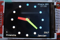
1st display : at 0, 3, 6, 9, 12, 15, 18, 21, 24 hour: classic clock with hands
2nd display : at 1, 4, 7, 10, 13, 16, 19, 22 hour: the time is display with bars
3rd display : at 2, 5, 8, 11, 14, 17, 20, 23 hour: the time is displayed with seven segments
See the pictures.
The time is set in a SETTING screen to adjust the time and date, and the alarm-clock.
The setting is done by 3 keys : “-“ key, “+” key and “ok” key, used in the SETTING screen.
The day and month in local languages are defined in the program, but need too much bytes in the FlashRom. The tinker will recompile the software with the wanted language (only uncomment its language).
The alarm-clock (when set) rings during 1 minute. (3 times if snooze function)
The alarm-clock may be set or not, by a manual switch (to sleep the week-end without setting adjustment) and it is possible to snooze 2 times (5 minutes each). In case of power leakage, the alarm-clock setting (hour and minute) is saved in the EEPROM.
The power of the LEDs of the TFT screen is automatically adjusted by a solar cell, which dims the LEDs, for people who need a complete darkness to sleep (like me!). The screen remains readable in the dark.
The RTC is a DS1302 with 32kHz Xtal, the microprocessor is the famous ATMega328P, the TFT display is an ILI9341, and the associated libraries.
I developed all the displays by myself, and it was interesting to understand the components/libraries operation. This program (if published by Elektor) is interesting to use for other software developments.
I also used the Streaming library to display some strings: very nice results and very simple to use.
The ports RX and TX are not used, if someone wants to modify this software and transmit information to another system.
I designed the hardware to allow programming by the ISP port: this will make easier modification of the screen display (mainly the colours?).
The total consumption is about 40 mA.
The FlashROM is used at 29500 bytes (very near with the bootloader!), and 1160 bytes of the RAM are used.
At the beginning, I wanted to build a 7 segments clock with Arduino . . . I found on Internet the little TFT screens (2.2’) able to display anything at very low price. But what to do first ? This clock ! It displays the time, but the way to display the time changes each hour.
1st display : at 0, 3, 6, 9, 12, 15, 18, 21, 24 hour: classic clock with hands
2nd display : at 1, 4, 7, 10, 13, 16, 19, 22 hour: the time is display with bars
3rd display : at 2, 5, 8, 11, 14, 17, 20, 23 hour: the time is displayed with seven segments
See the pictures.
The time is set in a SETTING screen to adjust the time and date, and the alarm-clock.
The setting is done by 3 keys : “-“ key, “+” key and “ok” key, used in the SETTING screen.
The day and month in local languages are defined in the program, but need too much bytes in the FlashRom. The tinker will recompile the software with the wanted language (only uncomment its language).
The alarm-clock (when set) rings during 1 minute. (3 times if snooze function)
The alarm-clock may be set or not, by a manual switch (to sleep the week-end without setting adjustment) and it is possible to snooze 2 times (5 minutes each). In case of power leakage, the alarm-clock setting (hour and minute) is saved in the EEPROM.
The power of the LEDs of the TFT screen is automatically adjusted by a solar cell, which dims the LEDs, for people who need a complete darkness to sleep (like me!). The screen remains readable in the dark.
The RTC is a DS1302 with 32kHz Xtal, the microprocessor is the famous ATMega328P, the TFT display is an ILI9341, and the associated libraries.
I developed all the displays by myself, and it was interesting to understand the components/libraries operation. This program (if published by Elektor) is interesting to use for other software developments.
I also used the Streaming library to display some strings: very nice results and very simple to use.
The ports RX and TX are not used, if someone wants to modify this software and transmit information to another system.
I designed the hardware to allow programming by the ISP port: this will make easier modification of the screen display (mainly the colours?).
The total consumption is about 40 mA.
The FlashROM is used at 29500 bytes (very near with the bootloader!), and 1160 bytes of the RAM are used.
Updates from the author