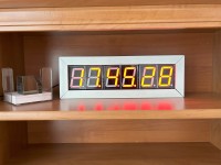
7-Segments 2.3-inch Clock based on ESP32 D1 mini and time receiving from NTP. The Article describes drivers and power voltage circuit for required voltage value. On the display there is shown Time and Date.
Introduction
This article describes a seven segment, 2.3-inch large display, that shows the time and date. Hardware is ready to show temperature, just coding need to be modified. My project is described here.
The exact time and date are obtained from the Network Time Protocol via Wi-Fi. For a smaller display, about 0.8-inch schematic diagram is very simple. Problems are with large segments, containing more LED's in series. In this case, the required voltage is higher than 5V. It is necessary to use some additional components and a special power supply.
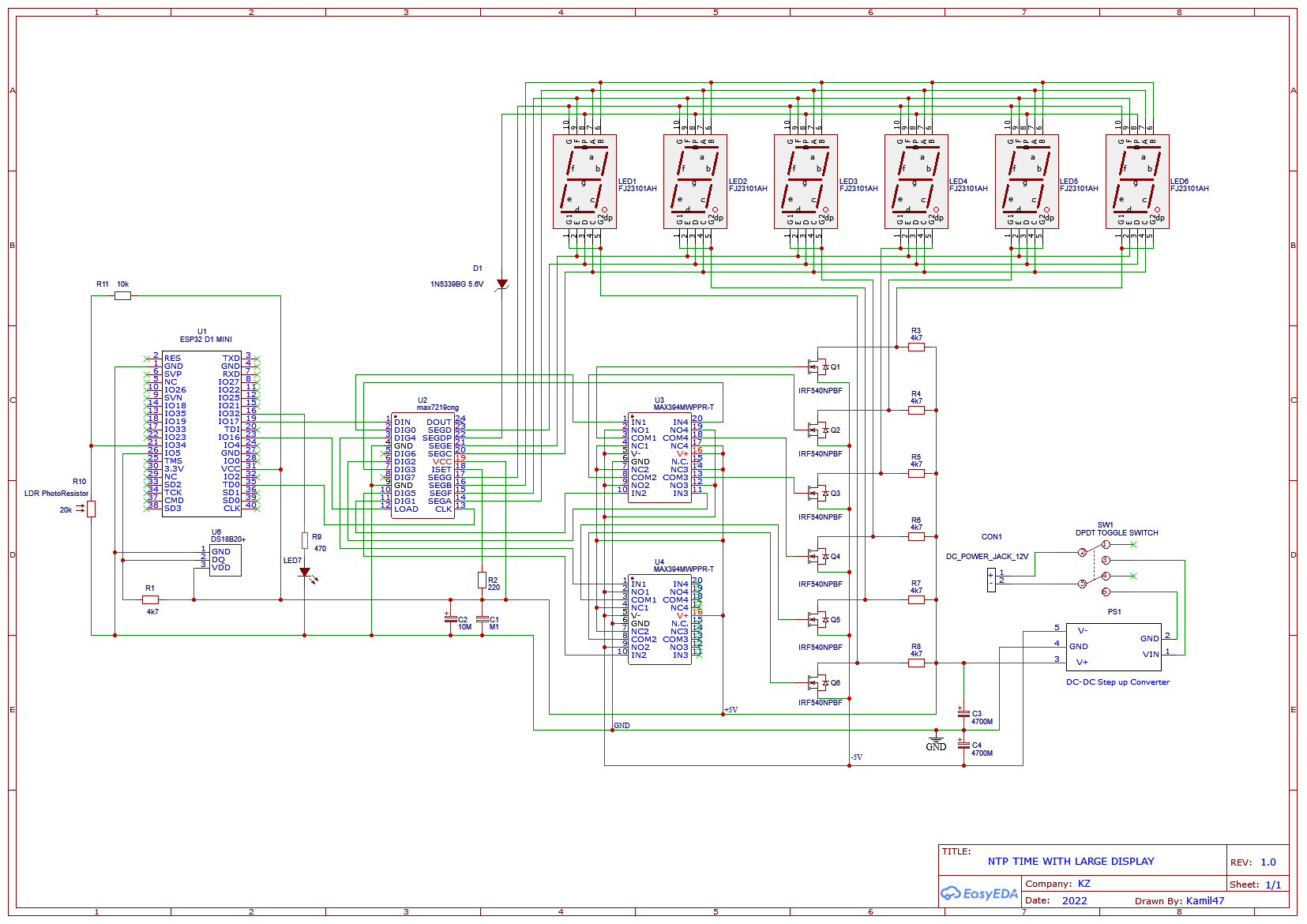
The main component is an ESP32 D1 mini, a microprocessor and some more Maxim IC's are used to drive displays: MAX7219 and two MAX333 components. The entire circuit is connected using the recommended connection from the Maxim Datasheet. The power supply is a DC-DC converter 5V to dual voltage +5V, GND, -5V.
Heart of the project is IC MAX7219 - U2 . It is driver for seven segments numeric LED display and is able to energize 8 digits by time multiplex. Display segments “a” to “f”, are connected directly to outputs pins 14-17 and pins 20, 21, 23, totally 7 pins. Pin 22 for decimal point need lower voltage, to prevent points from higher brightness. Zener diode D1 reduces the voltage for decimal point.
Individual digits are activated through common cathode, outputs DIGIT 0 – 5. Just 6 digits are used to display time in format: Hours. Minute. Seconds, exactly HH. MM. SS. Required voltage is provided by switches U3 and U4. Each IC MAX394 contains four single-pole and double-throw switches, which according to input signal, switch voltage on COM pin between NO and NC pins. This way is voltage from COM pin apply to gate of transistors and transistors switches display digits ON and OFF with voltage 10V. All transistors are IRF540N, N Channel Power MOSFET with ultra-low ON resistance. In ON state, resistance between Source and Drain is 0.04 ohm.
3 wire SPI serial interface connect the IC MAX7219 to microprocessor. Serial input for data is DATA pin 1, for CLK with max. 10MHz. Pin 13 and LOAD pin 12 loads incoming data. ISET pin 18 allow to adjust peak segment current by connected resistor R2. Resistor value calculation is described in Datasheet.
Diode LED7 detect problem with WI-FI signal, if On means error. LDR photo-resistor R10 sense ambient light and according of this level, adjust brightness of led segments. Temperature sensor DS18B20 is connected to pin IO5 of microprocessor U1. It is prepared to sense temperature, but code does not use and program it.
Construction
The size of PCB is determined by size of complete display – 6 digits. There is enough space for PTH technology and components.
On upper side lays six displays, mounted in sockets made of pinhead connectors. There is located LDR resistor and Error LED. All other parts are mounted on back side. On back side is placed switch such a way, that is accessible from front size. Switch was planned to be DPDT. I wanted to reduce size of switch, so finally I used smaller SPST, which is enough for safety reason. Next to the switch is power connector for plug adapter (main power220V/110V AC to 12V DC). It is a standard adapter 12V for current min. 0.5A.
Microprocessor and ICs are mounted in sockets. MCU is removable for programming. Power supply is switching PS, converter type DD39AJPA. Output voltage is adjustable. Board of PS is attached to PCB by 2 input and 3 output wires. Soldering points are designed for mentioned type of converter. On the market there are many similar types available. Output current must be about 0.5A min, more reliable are PS with 1A and higher current. Prototype was mounted inside aluminum frame via four screws.
Coding
In my project, there is used library for 7 segment Led display from Abaskin, GitHub. On mentioned link there are more information about functions, objects and other parts of library. For Arduino Ide, there must be file main with extension cpp changed to extension ino.. Two displays are shown in time sequences, one for time and one for date. Format of Date is DD. MM. YY (DD Day of Month, MM Month, YY Year-2000). Date display is activated at the end of the minute, in each the 52-th second and remain active for seven seconds. Timing for Time/Date display, can be modified by code.
Conclusion
The ambient temperature could be displayed, but I hesitate if it is useful. There must be some more time interval for temperature inside one minute. Is it worse instead of time information or not? Finally, I decided not to include the temperature. If somebody need it, is ready.
Generally, I can find many DIY digital clocks, but I was not successful to find clock with large 7 segments digits. From this point of view, and especially from the point of view of electronic problem solving, my project can be useful for many enthusiasts.
Login
No account yet?Register for free!
Forgot password?
Please enter your email address. Instructions for resetting the password will be emailed to you now.

Discussion (2 comments)