
Battery powered capacity meter
A capacity meter is more useful than you might expect.
By Pjotr1010
After finishing the FPPCe meter (see elsewhere on the ElektorLabs website) I discovered that a capacity meter is even more useful than expected. The FPPCe meter is fine when working on a prototype, especially when that prototype is partly build on a breadboard. Trying to test a suspect capacitor deep inside a malfunctioning piece of equipment is something else. The PFFCe meter does the job, but is not very ruggedized itself and requires external power. I decided to rebuild the meter as a battery powered capacity meter.
Too many times I have encountered equipment with exhausted batteries because the user had forgotten to switch the equipment off after use. So I wanted to implement an automatic switch off.
Requirements:
· Capacity measurement only
· Battery powered
· Robust housing
· Automatic switch off
· Easy to use
· Only through hole components
Here are the results.
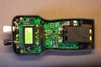
I have chosen for a Hammond box type 1553TTxxBAT. (xx may be GY for grey or BK for black). Not the cheapest, but strong and it has a battery compartment. The funny shape of the print was a challenge. I found it difficult to pinpoint the right spot for the hole in the box for the switch. No good reference points and a all walls curved. To solve this problem for copycats I changed the Kicad footprint of the used switches and added a small hole (1.1 mm in diameter) in the centre of the switch.
The Hammond box 1553TTxxBAT allows for mounting a PCB in the box and/or in the lid. The mounting holes in the box and in the lid are lined up. By mounting the PCB temporarily in the lid – before any component is placed! – the print now doubles as drilling jig. Use a 1 mm drill to mark the spot of the switch on the inside of the lid. The same trick is used to mark the corners of the cut-out for the display. My prototype print figuring on the photo’s does not yet have this feature, but it is in the gerber files and in the Kicad files. The meter became a simple handheld tool with a small display (2 lines of 8 characters) and a single pushbutton to operate it.
The measurement method is the same as in the FPPCe meter. The time needed to charge (or discharge) the capacitor under test between to voltage levels is measured. From that time the capacity is calculated. The charging resistor is 3M3. When it takes too much time (capacity over 250 nF) the measurement restarts with a charging resistor of 3k3. With that 3k3 a double measurement of the capacitor under test is done. One charging the capacitor, one discharging the capacitor. Both values are shown in the display. The upper line of the display shows the capacity measured with a rising voltage (charging) over the capacitor, the lower line of the display shows the capacity measured with a shrinking voltage (discharging) over the capacitor. See photo “Elco”.
Large capacitors, electrolytic types in particular, often show leakage and might require some current to rebuilt the insulation layer that forms the capacitor. When charging the capacitor this leads to loss of current for charging the capacitor, the capacitor seems to have a larger capacity. When discharging the capacitor the discharging goes faster, mainly because of the leakage. The capacitor seems to have a lower capacity. Good capacitors show two almost identical values. Sustaining different values indicate leakage. Values growing towards each other show the effect of rebuilding the insulation layer.
The meter has only one button for normal use. Shortly press the button and capacity measuring begins. A longer press on the button switches to measuring and displaying the battery voltage. Release of the button continues with capacity measurement. After 15 seconds the meter switches itself off. Only for measuring very small capacitors (< 100 pF) it might be helpful to readjust the meter for its own capacity. A “Zero-C” switch can be placed for this purpose.
More details of the meter are in the various PDF files. Also included are the Kicad files and the gerber files for print production.
After finishing the FPPCe meter (see elsewhere on the ElektorLabs website) I discovered that a capacity meter is even more useful than expected. The FPPCe meter is fine when working on a prototype, especially when that prototype is partly build on a breadboard. Trying to test a suspect capacitor deep inside a malfunctioning piece of equipment is something else. The PFFCe meter does the job, but is not very ruggedized itself and requires external power. I decided to rebuild the meter as a battery powered capacity meter.
Too many times I have encountered equipment with exhausted batteries because the user had forgotten to switch the equipment off after use. So I wanted to implement an automatic switch off.
Requirements:
· Capacity measurement only
· Battery powered
· Robust housing
· Automatic switch off
· Easy to use
· Only through hole components
Here are the results.
I have chosen for a Hammond box type 1553TTxxBAT. (xx may be GY for grey or BK for black). Not the cheapest, but strong and it has a battery compartment. The funny shape of the print was a challenge. I found it difficult to pinpoint the right spot for the hole in the box for the switch. No good reference points and a all walls curved. To solve this problem for copycats I changed the Kicad footprint of the used switches and added a small hole (1.1 mm in diameter) in the centre of the switch.
The Hammond box 1553TTxxBAT allows for mounting a PCB in the box and/or in the lid. The mounting holes in the box and in the lid are lined up. By mounting the PCB temporarily in the lid – before any component is placed! – the print now doubles as drilling jig. Use a 1 mm drill to mark the spot of the switch on the inside of the lid. The same trick is used to mark the corners of the cut-out for the display. My prototype print figuring on the photo’s does not yet have this feature, but it is in the gerber files and in the Kicad files. The meter became a simple handheld tool with a small display (2 lines of 8 characters) and a single pushbutton to operate it.
The measurement method is the same as in the FPPCe meter. The time needed to charge (or discharge) the capacitor under test between to voltage levels is measured. From that time the capacity is calculated. The charging resistor is 3M3. When it takes too much time (capacity over 250 nF) the measurement restarts with a charging resistor of 3k3. With that 3k3 a double measurement of the capacitor under test is done. One charging the capacitor, one discharging the capacitor. Both values are shown in the display. The upper line of the display shows the capacity measured with a rising voltage (charging) over the capacitor, the lower line of the display shows the capacity measured with a shrinking voltage (discharging) over the capacitor. See photo “Elco”.
Large capacitors, electrolytic types in particular, often show leakage and might require some current to rebuilt the insulation layer that forms the capacitor. When charging the capacitor this leads to loss of current for charging the capacitor, the capacitor seems to have a larger capacity. When discharging the capacitor the discharging goes faster, mainly because of the leakage. The capacitor seems to have a lower capacity. Good capacitors show two almost identical values. Sustaining different values indicate leakage. Values growing towards each other show the effect of rebuilding the insulation layer.
The meter has only one button for normal use. Shortly press the button and capacity measuring begins. A longer press on the button switches to measuring and displaying the battery voltage. Release of the button continues with capacity measurement. After 15 seconds the meter switches itself off. Only for measuring very small capacitors (< 100 pF) it might be helpful to readjust the meter for its own capacity. A “Zero-C” switch can be placed for this purpose.
More details of the meter are in the various PDF files. Also included are the Kicad files and the gerber files for print production.
Discussion (4 comments)