

Camel bag water indicator [ 140375 ]
By doing many mountain bike by hot weather (where I live), to carry a camel bag (or equivalent) is very common.During a trip, I was always frustrated to never know what is my quantity of water remain in the bag. I spent long to to think about this during these trips. I imagined to put a sensor inside the water bag, or some water debit sensor but nothing satisfy me.
By doing many mountain bike by hot weather (where I live), to carry a camel bag (or equivalent) is very common.
During a trip, I was always frustrated to never know what is my quantity of water remain in the bag. I spent long to to think about this during these trips. I imagined to put a sensor inside the water bag, or some water debit sensor but nothing satisfy me.
Until, I read the capacitive liquid detector from Paul Cordonnier in the July Elektor magazine. With this idea, no need to put sensor inside, outside could work. Great idea from Paul. Thanks a lot to him.
Begin to make some test with an 74HC4060 in 3.3V (for working with battery lithium) and with a plastic bag full/empty of water and it's work. There is a variation of the frequency. To make it more simple, I use the stage 11 (pin 1) which is given a frequency around 150hz when empty and 60hz when full.
The next step was how to manage the data and display a simple 4 leds level of the water level. The first idea was to use a simple uC, like 12F51x from Microchip. More easy but less funny that an hardware solution. It will be for the second version later.
So, how to display the data ? As the frequency is lower when it is full, the '1' is longer. Why not to use this signal to launch another 4060 to count during this time and using the diviser 128/256/512/1024 to display on led the level.
The CLR on the 4060 is low active and I wanted to save the current, 4060 with the sensor will power the second 4060. With a pulse at power on to clear all the stage, it can work by choosing the right frequency (which should be around 30khz).
To display, I use some high efficient led with 10k resistor. It is enough, even outside under sunshine. To make the sensor, I use some adhesive copper, put vertical (I tried horizontal but not successful), in opposite side.
To calibrate, the clock of the second 4060 can be change. It is little bit tricky to find the right adjustment between empty detection and full display.
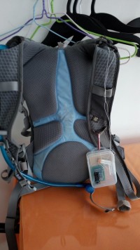
It is working, accurate enough for my need. I put it into a transparent box on my camel bag. Very light and useful.
Some new evolution plan:
- solar power panel to recharge the lithium battery
- Why not use an uC as plan at the beginning with a calibration for empty and full and avoid manual adjustment
Some pictures
Update August 16th:
-=> Add solar recharge for the LiPo battery.
To power the circuit, I'm using a small LiPo battery, 150mAh. To charge it, I use the same Ic than on the solarcam (other project) EUP8054. The only problem is this IC is in TSOP package and not easy to solder. I could test some other IC or make discrete one but this is an easy solution.
To charge, a small solar cell, 5V, 50mA, directly to the charger IC.
After few hours under sunshine, the battery was charged from 3.3v to 3.7V. I'm thinking to add another cell to increase the current.
Today, small trip, 2h bike, with some sunshine, end of afternoon. At the end, the battery was at same level than departure, 3.72V. So, even if the condition was not optimum, the battery didn t discharge.
The overall consumption of the circuit is 3mA. So, with all of this, autonomy should not be a problem. An external plug for USB charger can be plan when I'll do PCB
Next step will be to make the same circuit with uC...
Laurent
Discussion (1 comment)
Lucky 9 years ago
We picked up this project in our lab to design a small PCB for it. Unfortunately we can't find a (regular) source for the Li+-charger IC that Laurent uses in his original design, he suggested to replace it with a MAX1551 from Maxim Integrated.
-C2 is difficult to choose. It depends on the construction of the sensor (width and length and placement of the strips) and the kind (shape) of the camel bag used. On the original prototype C2 was increased to 1nf but it is really depending on the complete setup.
- The value of R4..R9 depend on the LEDs used. The author used very high efficiency (low current) LEDs and 10k resistors were just fine. With the LEDs used in our lab we had decrease the resistor values to 3k3 for a better visible display. With other LEDs, you may need to adjust these resistances.
For the sensor, use two strips of self-adhesive copper tape (15-20 cm long) or any flexible metal strip that can be attached or glued to the camel bag reservoir. Put them on both sides of the canister. Maybe it will also work with just wires as electrodes instead of strips, but we didn’t try that.
To link to the sensor to the PCB, simple twisted wires can be used (as short as possible), but shielded wire with a ground connection is preferred.
For the power supply the author used a small lithium battery, 100mAh. The most affordable solution is to use a 4.2V cell phone lithium battery and solder two wires to its connections.
About the solar cell, many of us will have some small 5V, 150mW (or more) panel suitable for this project. Can be something like this:
http://www.amazon.com/Small-Solar-Panel-5-5V-wires/dp/B00JOER89O/ref=pd_sim_lg_2?ie=UTF8&refRID=08FT0N99TXKFBB22MMPG#product-description-iframe
http://www.amazon.com/Solar-Module-System-Charger-44mmx35mm/dp/B00PI6TPRA
And of course many other suitable panels can be found on Ebay or other auction sites on the internet.
140375 Top and Bottom in black for DTP.pdf (11kb)
schematic-6.jpg (51kb)
Bill of materials (11kb)
Henk Apeldoorn 7 years ago
Als een inhoudelijke reactie geven en het stellen van een vraag geen enkel effect heeft dan kunnen wat mij betreft beide berichten verwijderd worden.
Met vriendelijke groet,
H. Apeldoorn
Henk Apeldoorn 8 years ago
Cruciaal bij een camelback is dat deze nagenoeg vacuum gezogen wordt als deze leeg raakt. De platen van de zelfbouwcondensator komen dan zeer dicht op elkaar te liggen hetgeen resulteerd in een hogere capaciteit. De zak gevuld met water geeft eveneens een hoge capaciteit vanwege de dieletriche constante van water. Deze twee effecten werken elkaar dus tegen waardoor er amper een reproduceerbaar verschil te meten is tussen een gevulde en leeggedronken camelback. Door de camelback te vullen met pvc buizen kan ik het terugvallen van de vorm enigzins tegengaan echter zonder in de buurt te komen van bruikbare specificaties.
Ik heb de capacitieve meetmethode op twee verschillende camelbacks uitgeprobeerd door de C te meten van gevuld naar volledig leeggedronken. De waarde schommelt rond de 250 pf. Dezelfde setup maar dan met een glazen fles geeft uitstekende resultaten. Mijn conclusie is dan ook dat deze methode alleen kan werken wanneer het volume en vorm van de waterdrager niet veranderd wanneer deze leeggedronken wordt.
Gaarne hoor ik hoe jullie dit opgelost hebben. Ik stel dat zoals het gepresenteerd wordt het niet betrouwbaar genoeg kan werken.
Met vriendelijke groet,
Henk