

Card Sound
Sound file player. Play sounds stored on an SD card with 2x 7W output power.
Searching for a powerful gong or acoustic notifier? The "Card Sound" consists of audio amplifier TDA7266 having 2x 7 W output, the AD converter CS4344, one STM32F401 and a slot for micro sd card. Objective is to play different sounds stored on an SD card. Current schematic has one TWI port for control. Amend other interfaces like RS-485, UART, SPI etc. is also possible.
Card Sound is playing now. Some unspectacular pictures have been added, but the sound is awesome :-) Software loads several wave files from FAT file system and feeds the CS4344 via DMA. Thanks to cheap SD card memory there is effectively no limit for number and size of wave files.
Card Sound is playing now. Some unspectacular pictures have been added, but the sound is awesome :-) Software loads several wave files from FAT file system and feeds the CS4344 via DMA. Thanks to cheap SD card memory there is effectively no limit for number and size of wave files.
Discussion (4 comments)

Hans Gans 7 years ago
As a maker I would prefer to build this project with existing assemblies. It is easier, cheaper and faster to realize.
So I found at ebay a mp3 player and a 30W power amp, together less than 8 EUR.
To built this project in this way would be quite awesome, as design software and layout all the time (only if unavoidable :=))
So I found at ebay a mp3 player and a 30W power amp, together less than 8 EUR.
To built this project in this way would be quite awesome, as design software and layout all the time (only if unavoidable :=))
Reply
Hans Gans 7 years ago
Inside the module there is no µC but only a little SO16 ASIC. Thus you can't get any software.
Of course, the benefits depends on what you want to do with it.
Neither the item is a "high end player" nor it has the flexibility of your own solution.
But on the other hand 8 to 320KHz bit rate and 8 to 44KHz sample frequency for wav is not so bad, isn't it?
Yes, you will find there only the IR remote input and a play switch. But should it be a problem to hack it? So you can reach more flexibility for building useable projects as "gong" or "personal alarm clock" etc. for less :=)
Reply

fasoft 7 years ago
These parts you have found are really cheap, indeed. Thanks for this hints. The picture looks like a class D amplifier with TDA8932. Very interesting if low power dissipation is important. According TAD8932s data sheet the power supply shall be > 20 VDC for passable distortion. For 12 VDC and 4 W output power THD+N seems to be about 10%. So, if 'higher' VDC is available, the module is a good choice :-)
Do you know if source code is available for the MP3 player? IrDA seems to be the only(?) control interface. Note, one/my purpose of Card Sound is to have flexibility of integrating own control protocol (via I²C or RS485 among others) and sound 'features' like fading etc.
Don't know if the MP3 player is also 24 bit capable (for higher quality together with 24 bit resolution wav files). Note, actual software v0.7 (not yet published) decodes 24 and 32 Bit with up to 128 kHz sampling rate.
Reply
Show more
2 Attachment(s)
2 Comment(s)


ClemensValens 8 years ago
Seems like a nice project. What exactly is its status? Do you have working software already? Do you have a working prototype?
Here is some advice unasked for: if you didn't order the PCB yet try to modify your design in such a way that all the SMD parts are on the same side. That will make assembly much easier (and cheaper).
Here is some advice unasked for: if you didn't order the PCB yet try to modify your design in such a way that all the SMD parts are on the same side. That will make assembly much easier (and cheaper).
Reply
fasoft 8 years ago
SW is WIP. PCB is already in place and parts will be soldered by hand next week. Reason for two side mounting is limited space in my electric cabinet the prototype is intended for.
But redesign of the layout is quite possible. TY for the hint. When prototype will work, I'll also estimate the needed CPU power and check if smaller MCU (like STM32F2xx) does meet the requirement.
But redesign of the layout is quite possible. TY for the hint. When prototype will work, I'll also estimate the needed CPU power and check if smaller MCU (like STM32F2xx) does meet the requirement.
Reply
Show more
1 Comment(s)
Updates from the author
fasoft 7 years ago
Happy New Year!
fasoft 8 years ago
RS 485 interface added,
almost all parts are placed on bottom side for production process simplification (except card holder and some THD parts),
Q8 corrected.
I have made these changes for the community to increase the 'connectivity' :-)
Feedback is very welcome.
Gerber files version 1.2 (59kb)
fasoft 8 years ago
fasoft 8 years ago
For demonstration, the elektor bus protocol is used, more precisely its 'A0' mode. Other protocols can be implemented, of course. The relevant place is market in the software module main.c.
The project is based on ST's CubeMX and is written in C. The CubeMX is quite useful especially for software prototyping. This is the experience I have made last weeks.
Hex file is already included. Re-compiling can be started by 'make' command in folder software/cube/SW4STM32. Installed arm-gcc toolchain is necessary for compiling. Currently, I use 'SW4' which can be loaded from the 'OpenSTM' web site. The installer of SW4 brings along all tools needed, like compiler, linker etc for the STM32F4xx.
Initial sources let the MCU main clock run at about 84 MHz, which is maximum speed for the STM32F401. Next steps are reducing the speed for several clock domains. Which would be easy with CubeMX. Volume control is currently not implemented. So, the wave files shall already have 'proper' level. If someone wants to control the volume, the Cortex-M4 based MCU has enought processor power to calculate the 16 bit values just-in-time. Lots of port pins are not yet used, so rotational encoder or other external controls can be added in general.
Some words regarding the SD card: I have tested with an older 2 GB and a faster 4 GB version of speed class 10. Both are working. Especially internal pull-ups of STM32F401 are suitable for the SDIO port lines. This saves PCP space for 5 external Rs.
The SD card shall have one partition which is 'FAT' formated. I have tested with FAT16 successfully.
Hope, I could draw interest. My next step is ... obviously: documentation. Some files have already inline documentation and are suited for applying doxygen.
Note: During initial software preparation further examples of use crossed my mind. The MCU has, such as, a RTC. Might as well to add a ..... having several sound themes. Of which more later.
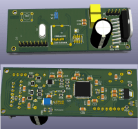
fasoft 8 years ago
Software loads several wave files from FAT file system and feeds the CS4344 via DMA. Thanks to cheap sd card memory there is effectively no limit for count and size of wave files.
Prototype v1.0 bottom side (276kb)
Schematic with some corrections (162kb)
corne.vandijk@home.nl 8 years ago
I was studying the schematics and saw something I not really understood! P7 Control pin 8 is going to the BSS84. I see there a P-channel Fet with the internal diode not in reversed order. That is not clear for me!
Can you explain the little circuit and why you used the Fet this way?
Thanks.
fasoft 8 years ago
You are right. Drain and Source of Q8 have to be swapped. I had already rotated Q8 on prototype/PCB (not visible in 49347.jpg because the picture was truncated on both sides during upload).
Q8 inverts the interrupt signal which is available at my home control 'network' (I2C/TWI bus). The 'network' has one additional wake-up line connected to pin 8 of P7 which is low active. STM32 can be woken from deep power down only by a _rising_ edge on PA0 however.
I will upload corrected schematic in the next days. I have also new software with some new features like volume control, fade out etc.
Regards, Falko