
Contact free DC voltage/electric field measurements
Employing a vibrating membrane measurement of DC voltages or electric fields from chrged items (ESD) are possile. The sensor can be homemade from household items. An Arduino type microcontroller is used to drive the measurement and proveide a readout.
Kind of reversing a condensor microphone by supplying "sound" as membrane vibrations it is possible to probe electric fields at the surface of the vibrating memebrane. More intedned as a kind of educational project I tried to realise this idea and explore the prospects of it.
The challenges are to detect the tiny induced currents (nA) while the sensing memebrane necesssarily is exposed to anvironmental fields. Also the vibration drive signal must be isolated.
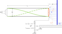
The latter could be achieved by coupling the sound from a tiny loudspeaker resonantly coupled by a 20-30cm air column to the vibrating Al foil membrane, which serves es sensing element.
The electrical signal is conditioned by an RC netwoork, amplified an filtered to reject 50Hz humm via two operation amplifier stages. The amplified signal then is fed to two synchronous detection stages that operate with 90 degrees phase shift. The two detected and preaveraged signal voltages then are read by an 16-bit ADC into the microcontroller, which perforrms additional averaging and computation of amplitude and phase of the signal.
On the other hand the microcontroller supplies the frequency signal for the vibration actuator: a tiin ylogic stage creates the 90 degree separated sampling signals for the sync detectors. One of this signal is amplified by a simple transistor stage to drive the miniature loudspeaker used a actuator.
Upon start the microcontroller scans a range of frequencies to determine the proper resonance (between 400 and 750 Hz).
With this setup it was possible too measure the voltage of an adjacent plate at a distance. The sensitivty is sufficient to acess voltages in the 100ds..1000ds Volts range with 20mm distance, a few volts with 2mm distance, electroostaic charges in the several kV range with 10cm.
The sensitivity strongly depends on the distance (the coupling capacitance involved) and alos on the strength of the excitation and resosnance. Therefore to interpret the measure voltages in terms of potential at the test object, an offset voltage may be applied to the membrane, the observed difference
in reading reveals the actual sensitivity.
In the present version the offset voltage must be supplied by an externalk source.
In the moment the setup rather has educational value than presenting a ready-to-use meter. However, it can be particular usefult to montor electrostatic charges and test items -even the own body- for being charged, e.g. to identify/prevent ESD damaging items or actions.
NOTE: be cautious with high voltages! When experimentig with charged surfaces use voltage sources with sufficiently high inner resistnace repectively current limitation (max a few micro Amps)!!
Updates from the author