
Cooking monitoring V3
The first version of this example is from 2018. My wife wanted to cook vegetables at low temperatures. The aim is to keep the temperature constantly low, i.e. cook at a temperature of around 60/80°C We discussed several variants of cooking monitoring to achieve the objective and we adopted the solution: Collect a basic electric plate. Combine an Arduino Nano, a thermocouple and its MAX6675, a potentiometer (for the setpoint), a 2X16 LCD (I2C equiped with PCF) and an SSR 10DA solid state relay to control
NOTA SEE :
Cooking Home Duo – PID Cooking Controller V3 + Bluetooth + SD
Author: Arduino47
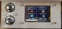
Platform: Arduino Mega 2560
Display: TFT 3.5" (ILI9486 / MyAff35 V3)
Sensors: 2× MAX6675 + K-type thermocouples
Control: 2× potentiometers (temperature setpoints)
Outputs: 2× PWM for electric hotplates
Communication: Bluetooth HC-05
Data Logging: SD card (CSV format compatible Excel)
Introduction
For this Christmas, my wife ordered a new version — one that could handle two plates and keep track of the cooking data.
So here is Cooking Home Duo V3, a complete PID-controlled dual plate manager, now enhanced with Bluetooth and SD logging.
Originally designed for a 2×16 LCD, the project evolved to a TFT 3.5" display for better ergonomics and readability.
Brief évolution
Cooking Home Duo V3 is a smart cooking controller that regulates two independent heating plates using PID control.
It reads the temperature from two thermocouples via MAX6675 modules and drives the heating power by PWM.
The system logs every measurement to the SD card or transmits it in real time over Bluetooth in CSV format.
Software & Libraries
PID control: using PID_v1 v1.2.0
Display: optimized MyAff35 V3 library (included)
Bluetooth communication: serial link (HC-05 module)
Data logging: Bluetooth communication
Standard SD library with CSV formatting
Compilation: zero warnings, lightweight, fully optimized code
Functional Description
For each channel (Cooking 1 & Cooking 2)
Real-time display of:
Measured temperature (°C)
Setpoint (target temperature)
PWM output in % (0–100%)
Bargraph of heating intensity
Independent regulation for both plates
Conservative/aggressive PID tuning based on error distance
Folder COOKING_HOME_DUO
COOKING_HOME_DUO_TFT_HC05_BT_CSV_SD.ino
Version V3+BT of the Arduino Mega 2560-based PID cooking controller represents
a significant upgrade to the project.
The entire codebase has been redesigned and optimized—for sensor readings, display handling, and PID computation alike.
use PID-1.2.0 and MyAff35 V3 library included in the zip. (BT_COOKING_HOME_EN English version, BT_COOKING_HOME_FR version Française)
-------- Main functions : --------
- Independent PID control for 2 heating zones
- Temperature reading via 2 thermocouple probes + MAX6675 (SPI bit banging)
- PWM control via SSR relay (Timer 1 or Timer 5 selectable)
- Control via potentiometers or Bluetooth HC-05
- Complete TFT display :
Measured temperature
Setpoint
PWM (%)
Cooking timer or PWM bar graph
Safety: PWM cutoff on overheating (MAX_TEMP_LOCK = 250°C)
Alert buzzer (fault / end of cooking)
-------- Bluetooth controls (break-resistant) -----------
-Cooking settings-
CGxxx: left setpoint (heating zone 1) e.g., CG115 → 115°C
CDxxx: right setpoint (heating zone 2) e.g., CD090 → 90°C
TGxxx: left timer (minutes) e.g., TG45 → 45 min
TDxxx: Right timer (minutes) e.g., TD120 → 2 h
-- Operating Modes--
MG: Left heating (68°C / 40 min)
MD: Right heating (68°C / 40 min)
SG: Left heating off
SD: Right heating off
GET: Sends the complete list of accepted commands
Qx: Returns to manual mode
CSV and Supervision Modes-
CSVx yy: CSV/BT or SD sending configuration
« Madame m’a souvent fait remarquer la lenteur de l’affichage... Alors je m’y suis mis sérieusement — et maintenant, vous en profitez aussi ! »
Cooking Home Duo – PID Cooking Controller V3 + Bluetooth + SD
Author: Arduino47
Platform: Arduino Mega 2560
Display: TFT 3.5" (ILI9486 / MyAff35 V3)
Sensors: 2× MAX6675 + K-type thermocouples
Control: 2× potentiometers (temperature setpoints)
Outputs: 2× PWM for electric hotplates
Communication: Bluetooth HC-05
Data Logging: SD card (CSV format compatible Excel)
Introduction
For this Christmas, my wife ordered a new version — one that could handle two plates and keep track of the cooking data.
So here is Cooking Home Duo V3, a complete PID-controlled dual plate manager, now enhanced with Bluetooth and SD logging.
Originally designed for a 2×16 LCD, the project evolved to a TFT 3.5" display for better ergonomics and readability.
Brief évolution
Cooking Home Duo V3 is a smart cooking controller that regulates two independent heating plates using PID control.
It reads the temperature from two thermocouples via MAX6675 modules and drives the heating power by PWM.
The system logs every measurement to the SD card or transmits it in real time over Bluetooth in CSV format.
Software & Libraries
PID control: using PID_v1 v1.2.0
Display: optimized MyAff35 V3 library (included)
Bluetooth communication: serial link (HC-05 module)
Data logging: Bluetooth communication
Standard SD library with CSV formatting
Compilation: zero warnings, lightweight, fully optimized code
Functional Description
For each channel (Cooking 1 & Cooking 2)
Real-time display of:
Measured temperature (°C)
Setpoint (target temperature)
PWM output in % (0–100%)
Bargraph of heating intensity
Independent regulation for both plates
Conservative/aggressive PID tuning based on error distance
Folder COOKING_HOME_DUO
COOKING_HOME_DUO_TFT_HC05_BT_CSV_SD.ino
Version V3+BT of the Arduino Mega 2560-based PID cooking controller represents
a significant upgrade to the project.
The entire codebase has been redesigned and optimized—for sensor readings, display handling, and PID computation alike.
use PID-1.2.0 and MyAff35 V3 library included in the zip. (BT_COOKING_HOME_EN English version, BT_COOKING_HOME_FR version Française)
-------- Main functions : --------
- Independent PID control for 2 heating zones
- Temperature reading via 2 thermocouple probes + MAX6675 (SPI bit banging)
- PWM control via SSR relay (Timer 1 or Timer 5 selectable)
- Control via potentiometers or Bluetooth HC-05
- Complete TFT display :
Measured temperature
Setpoint
PWM (%)
Cooking timer or PWM bar graph
Safety: PWM cutoff on overheating (MAX_TEMP_LOCK = 250°C)
Alert buzzer (fault / end of cooking)
-------- Bluetooth controls (break-resistant) -----------
-Cooking settings-
CGxxx: left setpoint (heating zone 1) e.g., CG115 → 115°C
CDxxx: right setpoint (heating zone 2) e.g., CD090 → 90°C
TGxxx: left timer (minutes) e.g., TG45 → 45 min
TDxxx: Right timer (minutes) e.g., TD120 → 2 h
-- Operating Modes--
MG: Left heating (68°C / 40 min)
MD: Right heating (68°C / 40 min)
SG: Left heating off
SD: Right heating off
GET: Sends the complete list of accepted commands
Qx: Returns to manual mode
CSV and Supervision Modes-
CSVx yy: CSV/BT or SD sending configuration
« Madame m’a souvent fait remarquer la lenteur de l’affichage... Alors je m’y suis mis sérieusement — et maintenant, vous en profitez aussi ! »
Updates from the author