
DIY programmable (SCPI) bench power supply
An open source (software and hardware) power supply that bridges the gap between DIY/hobbyists/education
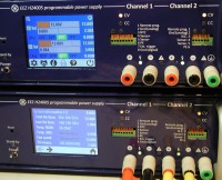
The EEZ H24005 is a dual channel fully programmable (Arduino Due controlled) power supply. It is characterized by modular and compact design, broad capabilities and, 3.2" TFT color touch-screen display. The EEZ H24005 is a maker and hacker friendly project that anyone can build and modify at home.
Two floating power channels are isolated and thanks to built in power relays can be safely (controlled by MCU) connected in series or parallel to provide up to 80 V and 10 A on the output. A serial hybrid topology is used with SMPS pre-regulator and linear post-regulation. The pre-regulator thanks to LTC3864 controller can work in 100% duty cycle mode and can be by-passed and power channel can enter so-called "low ripple" that is MCU controlled to stay within SOA of regulated elements. Additionally channel's SMPS regulators are synchronized and driven with anti-phase (180 degrees) signals that helps maintain low ripple when outputs are connected in parallel.
All circuits are located on three different PCBs:
Internal wiring is reduced to bare minimum to simplify assembly. Therefore Power boards are directly connected to the Arduino Shield and thanks to high voltage SMPS power and bias pre-regulators only one power input is used (hence one connecting cable is required!). Power board accept both AC and DC power input. In first case that could be AC mains power transformer otherwise AC/DC power module is used.
The Arduino shield is designed to carry Arduino board (Due or 100% compatible, possibly STAT-OTTO, etc.), TFT touch-screen display and all front panel connectors (push-in, power binding posts) and various LED indicators.
Main hardware features:
It's now highly mature but still ongoing project since we are continue with adding new functionality into firmware. It comes with comprehensive set of SCPI commands. Thanks to SCPI it’s possible to remotely program and monitor power supply. For the local control a color TFT touchscreen with intuitive GUI is used. All menu pages are designed in the EEZ Studio (screenshot), a visual toolkit for rapid GUI development that will be also available as a free and open source in coming months and can be used in many other projects.
Main firmware M2 features:
Thanks to EEZ Software Simulator one can evaluate all functionality and even start modifying existing or adding features into firmware (an Arduino sketch!) without having physical unit on disposal. The EEZ Software Simulator is cross-platform and can be compiled and run on Linux, Windows and OS X. It’s a great tool developed to simplify debugging and speed up development process.
Hardware details (i.e. Eagle and Gerber files, BOM, mechanical drawing, building instructions, etc.) can be found on the GitHub here, and firmware here.
Two floating power channels are isolated and thanks to built in power relays can be safely (controlled by MCU) connected in series or parallel to provide up to 80 V and 10 A on the output. A serial hybrid topology is used with SMPS pre-regulator and linear post-regulation. The pre-regulator thanks to LTC3864 controller can work in 100% duty cycle mode and can be by-passed and power channel can enter so-called "low ripple" that is MCU controlled to stay within SOA of regulated elements. Additionally channel's SMPS regulators are synchronized and driven with anti-phase (180 degrees) signals that helps maintain low ripple when outputs are connected in parallel.
All circuits are located on three different PCBs:
- AUX PS module
- Power board (one per channel)
- Arduino Shield
Internal wiring is reduced to bare minimum to simplify assembly. Therefore Power boards are directly connected to the Arduino Shield and thanks to high voltage SMPS power and bias pre-regulators only one power input is used (hence one connecting cable is required!). Power board accept both AC and DC power input. In first case that could be AC mains power transformer otherwise AC/DC power module is used.
The Arduino shield is designed to carry Arduino board (Due or 100% compatible, possibly STAT-OTTO, etc.), TFT touch-screen display and all front panel connectors (push-in, power binding posts) and various LED indicators.
Main hardware features:
- 2 x 40 V, 5 A per channel (hackable to e.g. 30 V or up to 50 V, 3 V or 4 A)
- Voltage and current control in 10 mV/mA or better (thanks to 16-bit DAC / 15-bit ADC)
- Remote voltage sense built-in with reverse polarity protection
- Remote voltage programming with built-in OVP protection
- Output enable and down-programmer circuit
- Cooling with passive heatsink and speed controlled 60 mm fan
- AC input voltage protection
- AC soft-start/stand-by circuit
- USB (could be isolated), Ethernet (W5500 chip)
- RTC with supercap backup
- External EEPROM
- Power relays for MCU controlled power outputs connections
- Signal relays for MCU controlled voltage sense connections
- Digital I/O: 1 x input (protected, 3.3 and 5 V level logic)
- Battery NTC input (opto-isolated with V/F converter)
It's now highly mature but still ongoing project since we are continue with adding new functionality into firmware. It comes with comprehensive set of SCPI commands. Thanks to SCPI it’s possible to remotely program and monitor power supply. For the local control a color TFT touchscreen with intuitive GUI is used. All menu pages are designed in the EEZ Studio (screenshot), a visual toolkit for rapid GUI development that will be also available as a free and open source in coming months and can be used in many other projects.
Main firmware M2 features:
- Remote control with SCPI commands via serial (USB) or Ethernet
- Local control using color touch-screen display
- Touch-screen calibration wizard
- Voltage and current calibration wizard
- 10 user profiles
- Various protections: OCP, OVP, OPP, OTP
- Output value limits
- Date/time settings
- Ethernet settings
- "Low-ripple" mode control
- Various output values display modes (digits, horizontal and vertical bar graph)
- Various output values programming: keypad, step, slider
- Remote sensing, remote programming control
- Event viewer
Thanks to EEZ Software Simulator one can evaluate all functionality and even start modifying existing or adding features into firmware (an Arduino sketch!) without having physical unit on disposal. The EEZ Software Simulator is cross-platform and can be compiled and run on Linux, Windows and OS X. It’s a great tool developed to simplify debugging and speed up development process.
Hardware details (i.e. Eagle and Gerber files, BOM, mechanical drawing, building instructions, etc.) can be found on the GitHub here, and firmware here.
Updates from the author