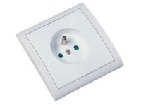
Earth-phase-neutral detector

With this little tool, id like to make a simple, but efficient monitor to see if all wiring in a power socket is connected right. In general, a single phase power socket and be wired in 2 ways:1. PHASE/PHASE/EARTH: we get 2 phases; 230V between them. If the earth is connected right, we measure 115V between both phases and earth.
With this little tool, id like to make a simple, but efficient monitor to see if all wiring in a power socket is connected right. In general, a single phase power socket and be wired in 2 ways:
1. PHASE/PHASE/EARTH: we get 2 phases; 230V between them. If the earth is connected right, we measure 115V between both phases and earth.
2. PHASE/NEUTRAL/EARTH: we get 1 phase, 1 neutral; 230V between them If the earth is connected right, we measure 230V between phase and earth. Between neutral and earth we measure 0V.
Id like to make a circuit that detects what type of mains connection we get. Also Id like to see if the earth is properly connected. The circuit is made of 3 double coloured led's, 4 zenerdiodes and 3 1N4007 diodes.
Idea is to measure voltages between earth, neutral and phase. I use the red leds with a series resistor of 68K: 3.35mA for each led at 230V
The green led only lights up when the voltage is +211V (2 zeners 51V + 160V): 2.8mA for each led at 230V.
I keep the currents quite low to avoid the earth leak detection trips.... D5 and D6 avoid reverse currents through the leds.
If a "PHASE PHASE EARTH" socket is wired right, leds light up as follows:
L1 GREEN (115V)
L2 GREEN (115V)
L3 YELLOW (230V)
If a "PHASE NEUTRAL EARTH" socket is wired right, leds light up as follows:
L1 OFF (0V) or YELLOW (230V)
L2 YELLOW (230V) or OFF (0V)
L3 YELLOW (230V)
>> When earth is not connected, only L3 lights up !
I will post my prototype soon, schematics attached now!
UPDATE: I add a 1N4007 over each led, to avoid reverse (leak) currents.


Updates from the author
frederik 9 years ago
I will build this pcb, and post the test results soon.
earth2schema.pdf (24kb)
00 Fre - earth.zip (60kb)
brandie 8 years ago
Mikroprofessor 8 years ago